


Voltage-To-Frequency Converter With Optocoupler
#voltage-to-frequency
#optocoupler
#RC4151
#LM131
#signal conversion
#analog
#frequency modulation
#circuit design

Description: In this circuit, a Raytheon RC4151 or National LM131 is utilized alongside an optocoupler for applications where input-to-output isolation is desirable. Circuit values are indicated in the figure for various applications.
The circuit employs a Raytheon RC4151 or National LM131, both of which are precision voltage references known for their stability and low drift characteristics. These components are integrated with an optocoupler to ensure electrical isolation between the input and output, which is crucial in preventing ground loops and protecting sensitive components from voltage spikes or noise that may be present in the input signal.
The optocoupler serves as a crucial interface that transmits signals while maintaining isolation. It typically consists of a light-emitting diode (LED) and a photodetector, such as a photodiode or phototransistor, housed within a single package. When an input voltage is applied to the LED, it emits light, which is detected by the photodetector on the output side, thus transferring the signal without a direct electrical connection.
The circuit values, which are specified in the accompanying figure, can vary depending on the specific application requirements, such as the desired input and output voltage levels, current ratings, and response times. These parameters must be carefully selected to optimize the performance of the circuit while ensuring reliable operation under varying conditions.
In applications where isolation is paramount, such as in industrial control systems, medical devices, or communication equipment, this configuration provides an effective solution. It allows for the safe transmission of signals across different voltage domains, ensuring that the integrity of the sensitive output circuitry is maintained. In this circuit, a Raytheon RC4151 or National LM131 is used in conjunction with an optocou pler for applications where input-to-output isolation is desirable. Circuit values are shown in the figure for various applications.
The circuit employs a Raytheon RC4151 or National LM131, both of which are precision voltage references known for their stability and low drift characteristics. These components are integrated with an optocoupler to ensure electrical isolation between the input and output, which is crucial in preventing ground loops and protecting sensitive components from voltage spikes or noise that may be present in the input signal.
The optocoupler serves as a crucial interface that transmits signals while maintaining isolation. It typically consists of a light-emitting diode (LED) and a photodetector, such as a photodiode or phototransistor, housed within a single package. When an input voltage is applied to the LED, it emits light, which is detected by the photodetector on the output side, thus transferring the signal without a direct electrical connection.
The circuit values, which are specified in the accompanying figure, can vary depending on the specific application requirements, such as the desired input and output voltage levels, current ratings, and response times. These parameters must be carefully selected to optimize the performance of the circuit while ensuring reliable operation under varying conditions.
In applications where isolation is paramount, such as in industrial control systems, medical devices, or communication equipment, this configuration provides an effective solution. It allows for the safe transmission of signals across different voltage domains, ensuring that the integrity of the sensitive output circuitry is maintained. In this circuit, a Raytheon RC4151 or National LM131 is used in conjunction with an optocou pler for applications where input-to-output isolation is desirable. Circuit values are shown in the figure for various applications.

Electronic Projects
This program includes circuit design CAD, simulation, and auto-routing PC layout. PSPICE is also utilized at Unisys, which offers more capabilities but costs six times as much and requires annual renewal. With these requirements and others in mind, a variation...

Interfacing High Power Load to Logic Level with Optocoupler
Interfacing high power loads can be accomplished in various ways, including the use of voltage divider resistors, transformers, or optocouplers. The circuit illustrated below employs the optocoupler method. This optocoupler facilitates logic level translation with flexible input, accommodating a wide...

Analog IO Protection
The I/O Filter Wildcard offers an efficient platform for prototyping analog circuits or for filtering, conditioning, or protecting the I/O lines of other Wildcards. It features twenty-four I/O lines that can be independently filtered or combined in customized configurations. To...

Voltage-to-frequency converter
The D169 functions as a level detector, offering complementary outputs. An operational amplifier (op amp) is employed to integrate the input signal Vin, utilizing a time constant defined by the resistor R1 and capacitor C1. A negative input signal generates...

Voltage-to-Frequency And Frequency-to-Voltage Converter
The AD652 Synchronous Voltage-to-Frequency Converter (SVFC) is a robust component designed for precision analog-to-digital conversion, featuring a typical nonlinearity of 0.002% (maximum of 0.005%) at an output frequency of 100 kHz. Its inherent monotonicity in the transfer function and the...
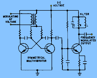
Methods of frequency modulation
The circuit depicted in figure 2-6 and discussed in previous sections serves illustrative purposes only and is not practical in real-world applications. Nevertheless, the fundamental principle involved—the variation in reactance of an oscillator circuit in response to modulating voltage—represents one...

Linear optocoupler for instrumentation
A dual optocoupler is utilized in a configuration that maintains the same current across the LEDs. Assuming comparable optocoupler characteristics, the output voltage must match the non-inverting input voltage. Given that the operational amplifier operates within a closed loop, the...

Optocoupler circuits
This circuit is a TTL-to-TTL isolator circuit. The driver circuit is an open-collector TTL inverter (U1). When the input is high, the output of the inverter is low. Thus, when the input is high, the output of U1 grounds the...
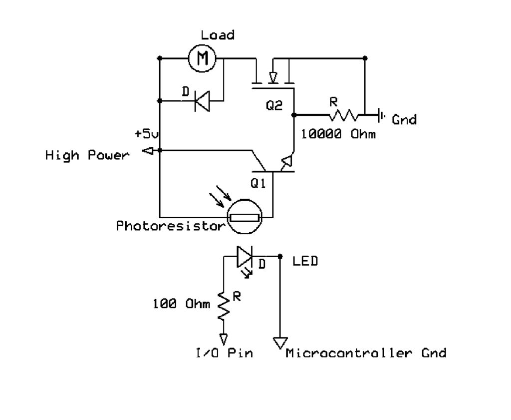
Optocoupler
This circuit utilizes a microcontroller I/O pin to control a high-power load, such as a motor, while preventing potential damage to the sensitive circuits of the microcontroller.
The described circuit employs a microcontroller to manage a high-power load, typically a motor,...