



Buck Converter Design
The top MOSFET switches on creating a short circuit between the input voltage (IN) and the left hand side of the inductor, L1. The inductor current ramps up acc...
Buck Converter Design
The top MOSFET switches on creating a short circuit between the input voltage (IN) and the left hand side of the inductor, L1. The inductor current ramps up acc...

Boost Converter Design
Ignore components C1, C2, R3. The MOSFET, Q1, switches on creating a short circuit between the right hand side of the inductor, L1, and 0V. Thus a fixed voltage...
Boost Converter Design
Ignore components C1, C2, R3. The MOSFET, Q1, switches on creating a short circuit between the right hand side of the inductor, L1, and 0V. Thus a fixed voltage...

Voltage frequency converter circuit composed of AD654
The circuit shown in the figure is low-cost voltage frequency converter (VFC) with AD654. Connecting to necessary components Rl and Cl according to figure will ...
Voltage frequency converter circuit composed of AD654
The circuit shown in the figure is low-cost voltage frequency converter (VFC) with AD654. Connecting to necessary components Rl and Cl according to figure will ...

Stabilized voltage inverter 12V-220V 200W
Stabilized voltage inverter 12V-220V 200W is shown in the following diagram. It can adopt existing dual 12V-200W mains transformer. But its invert efficiency is...
Stabilized voltage inverter 12V-220V 200W
Stabilized voltage inverter 12V-220V 200W is shown in the following diagram. It can adopt existing dual 12V-200W mains transformer. But its invert efficiency is...

Self-control digital inverter power supply circuit diagram:1.2V rising to 9V
It does not require the establishment of a separate power switch or transformation to switches in the table. The circuit has the advantages of low power consump...
Self-control digital inverter power supply circuit diagram:1.2V rising to 9V
It does not require the establishment of a separate power switch or transformation to switches in the table. The circuit has the advantages of low power consump...
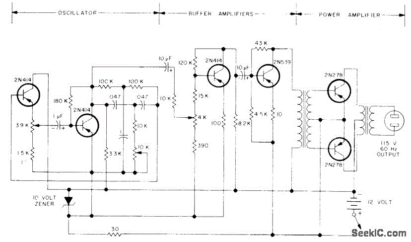
100W SINE AT 60Hz
Consists essentially of 60-Hz sine-wave oscillator with 10K frequency-control pot, two buffer stages, and push-pull power amplifier. Circuit eliminates noise pr...
100W SINE AT 60Hz
Consists essentially of 60-Hz sine-wave oscillator with 10K frequency-control pot, two buffer stages, and push-pull power amplifier. Circuit eliminates noise pr...

Zero-voltage zero-current switch three-level DC converter
In order to remove circulating current of zero-voltage switch three-level DC converter in zero state, we come up with kind of zero-voltage zero-current switch t...
Zero-voltage zero-current switch three-level DC converter
In order to remove circulating current of zero-voltage switch three-level DC converter in zero state, we come up with kind of zero-voltage zero-current switch t...

VFC62 voltage / frequencyfrequency / voltage converter circuit
VFC62 voltage / frequency,frequency / voltage converter can easily convert analog signals into digital signals.The digital output uses the form of open collecto...
VFC62 voltage / frequencyfrequency / voltage converter circuit
VFC62 voltage / frequency,frequency / voltage converter can easily convert analog signals into digital signals.The digital output uses the form of open collecto...

voltage conversion circuit composed of VFC320
Figure 1-22 (a) shows the circuit which could convert 0-+lOV input voltage Ui into the pulse with 0 -1OOkHz output frequency, and pin 7 of VFC320 is connected a...
voltage conversion circuit composed of VFC320
Figure 1-22 (a) shows the circuit which could convert 0-+lOV input voltage Ui into the pulse with 0 -1OOkHz output frequency, and pin 7 of VFC320 is connected a...

voltage conversion circuit composed of NJM4558
Figure 1-42 (a) is a voltage / current conversion circuit, and it can convert 0-lOV input voltage into 4-2OmA output current. Adjusting RP2 could make Ui = 0, I...
voltage conversion circuit composed of NJM4558
Figure 1-42 (a) is a voltage / current conversion circuit, and it can convert 0-lOV input voltage into 4-2OmA output current. Adjusting RP2 could make Ui = 0, I...