


10 led VU Meter using LM3915
#LED
#LM3915
#VU Meter
#TL071
#audio level indicator
#precision rectifier
#10 LED
#visual indicator
#level measurement
#switch control

Description: The circuit diagram represents a straightforward circuit-level indication featuring 10 LEDs. It utilizes a series of half-wave rectification controlled by the precision operational amplifier IC2 TL071. The LM3915 integrated circuit is employed to manage the LEDs, functioning as a VU meter indicator. The LM3915 can control up to 10 LEDs. A switch (S1) allows the selection of the LED indication level, ranging from 60 mV to 25 V.
The described circuit operates on a principle of visual signal representation using a VU meter configuration. The core component, the LM3915, is a dot/bar graph display driver that can illuminate up to 10 LEDs in response to an input voltage. This IC is particularly suited for audio level indication, providing a clear visual representation of signal strength.
The circuit begins with the input signal, which is fed into the TL071 operational amplifier. This op-amp is configured for half-wave rectification, ensuring that only the positive half of the input waveform is processed. This rectified output is then fed into the LM3915, which interprets the voltage level and activates the corresponding number of LEDs based on the input signal strength.
The switch S1 introduces versatility to the circuit by allowing users to select different voltage ranges for indication. This feature is essential for applications where varying signal levels need to be monitored. The circuit can effectively display levels from as low as 60 mV, suitable for low-level audio signals, up to 25 V, accommodating higher voltage signals.
In terms of component selection, the TL071 is favored for its low noise and high precision, making it ideal for audio applications. The LM3915's ability to drive multiple LEDs without additional components simplifies the design and reduces potential points of failure.
Overall, this circuit design provides a reliable and visually intuitive method for monitoring signal levels, making it suitable for various electronic applications, including audio equipment, signal processing, and general voltage level monitoring.Circuit diagram is a very simple circuit-level indication, with 10 Led. Used a series of half-wave rectification of precision around IC2 TL071, with a single. LM3915 IC is used to control the led, as an indicator VU Meter. LM3915 can be controlled 10 led. With the switch S1, we can choose an indication from the LED. Level mV into a 60-1st, 25 V. T he following is a schematic drawing:
The described circuit operates on a principle of visual signal representation using a VU meter configuration. The core component, the LM3915, is a dot/bar graph display driver that can illuminate up to 10 LEDs in response to an input voltage. This IC is particularly suited for audio level indication, providing a clear visual representation of signal strength.
The circuit begins with the input signal, which is fed into the TL071 operational amplifier. This op-amp is configured for half-wave rectification, ensuring that only the positive half of the input waveform is processed. This rectified output is then fed into the LM3915, which interprets the voltage level and activates the corresponding number of LEDs based on the input signal strength.
The switch S1 introduces versatility to the circuit by allowing users to select different voltage ranges for indication. This feature is essential for applications where varying signal levels need to be monitored. The circuit can effectively display levels from as low as 60 mV, suitable for low-level audio signals, up to 25 V, accommodating higher voltage signals.
In terms of component selection, the TL071 is favored for its low noise and high precision, making it ideal for audio applications. The LM3915's ability to drive multiple LEDs without additional components simplifies the design and reduces potential points of failure.
Overall, this circuit design provides a reliable and visually intuitive method for monitoring signal levels, making it suitable for various electronic applications, including audio equipment, signal processing, and general voltage level monitoring.Circuit diagram is a very simple circuit-level indication, with 10 Led. Used a series of half-wave rectification of precision around IC2 TL071, with a single. LM3915 IC is used to control the led, as an indicator VU Meter. LM3915 can be controlled 10 led. With the switch S1, we can choose an indication from the LED. Level mV into a 60-1st, 25 V. T he following is a schematic drawing:

A Simple VU Meter using LM3914
This simple VU meter can be utilized in a variety of projects. Since traditional electromagnetic VU meters are either no longer available or prohibitively expensive, this design employs the LM3914 integrated circuit and ten LEDs, allowing for versatile application in...
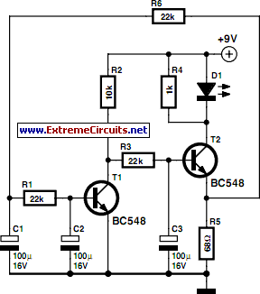
Smooth FlasherCircuit
Standard LED flashers activate the LED in a rapid on-off sequence, which can become bothersome over time. The circuit presented here offers a more gradual illumination effect.
This circuit utilizes a simple design to create a soft flashing LED effect, which...

Economical Desk Lamp For Camping
This LED lamp was originally designed for use in a budget solar-charged 12V electrical system. It provides sufficient brightness for comfortable reading at night.
The LED lamp operates on a 12V power supply, making it suitable for integration into solar-powered systems...

LED Dimmer Lighting
A dimmer for individual LED bulbs. LEDs (light emitting diodes) are very sensitive components; exceeding their rated current or voltage can drastically reduce their lifespan from over 50,000 hours to mere microseconds. LEDs are current-driven, meaning that the intensity of...
Six LED Stereo VU Display
The following circuit is a six LED stereo VU display diagram that is constructed using the Dot/Bar Display Driver IC LM3915. This VU display should be connected before the amplifier module circuit. It can be connected at the pre-amp output,...

LED VU Meter
The circuit utilizes two quad voltage comparators (LM339) to illuminate a series of eight LEDs that indicate volume levels. Each of the eight comparators is biased at progressively higher voltages established by a voltage divider, allowing the lower right LED...

LED-Microscope
This instruction outlines the process of converting a standard microscope that uses a light bulb to LED illumination. A mobile phone charger can be utilized as the power supply due to the significantly lower power consumption of LEDs. This eliminates...

15V LED Power Supply
This circuit illustrates a 1.5V LED power supply circuit diagram. Features include the requirement of a step-up transformer (40:60) for easy provision. Components include an integrated circuit (IC).
The described circuit functions as a power supply specifically designed for driving LEDs...

Phone Message Flasher
This circuit flashes an LED to indicate that a phone rang during the user's absence. A differential amplifier with hysteresis (Q1, Q2, and Q3) detects high line voltage (ringing), which activates Q4, a multivibrator composed of Q5 and Q6, and...