


6 Volt Automatic Emergency Light Battery
#emergency light
#battery charger
#overcharge protection
#relay
#inverter
#NE555
#automatic switching
#mains failure
#LED

Description: This circuit is an IC-controlled emergency light. It automatically switches on the light during a mains failure and includes a battery charger with overcharge protection. When the mains power is absent, relay RL2 is in a de-energized state, supplying battery power to the inverter section through its normally closed contacts and switch S1. The inverter section contains IC2 (NE555), which operates in a stable manner to generate sharp pulses at a frequency of 50 Hz for driving the MOSFETs. The output from IC3 is directly fed to the gate of MOSFET (T4), while it is applied to MOSFET (T3) through gate transistor T2. The amplifier designed around MOSFETs T3 and T4 operates in a push-pull configuration. The output across the secondary of transformer X2 can easily drive a 230-volt, 20-watt fluorescent tube. If continuous light is not required during mains failure, switch S1 can be turned off. The battery overcharge protection circuit is built around IC1 (LM308). Its non-inverting pin is held at a reference voltage of approximately 6.9 volts, obtained using diode D5 (1N4148) and 6.2-volt zener diode D6. The inverting pin of IC1 is connected to the positive terminal of the battery. When mains power is available, the output of comparator IC1 is high, unless the battery voltage exceeds 6.9 volts. In this state, transistor T1 is forward biased, energizing relay RL1, which keeps the battery charging through the normally open contacts of relay RL1 and current limiting resistor R2. When the battery voltage exceeds 6.9 volts (indicating an overcharged condition), the output of IC1 goes low, de-energizing relay RL1 and stopping further battery charging. MOSFETs T3 and T4 should be mounted on suitable heat sinks.
The described circuit functions as a reliable emergency lighting solution, utilizing an integrated circuit (IC) to manage both the charging of the battery and the operation of the inverter. The NE555 timer (IC2) serves as a pulse generator, which is crucial for the operation of the MOSFETs T3 and T4. These MOSFETs are responsible for converting the DC voltage from the battery into the AC voltage needed to power a fluorescent tube during a power outage. The push-pull configuration of the amplifier ensures efficient use of the available power, allowing for a stable output.
The overcharge protection mechanism is vital for maintaining the longevity and safety of the battery. The LM308 comparator (IC1) continuously monitors the battery voltage, ensuring that charging ceases once the voltage exceeds the set threshold of 6.9 volts. This is achieved through a simple voltage divider formed by the zener diode D6 and the 1N4148 diode D5, which provides a stable reference voltage. The relay RL1 acts as a switch that controls the charging circuit, and its operation is critical for preventing damage to the battery due to overcharging.
In addition, the use of suitable heat sinks for the MOSFETs T3 and T4 is necessary to dissipate heat generated during operation, thereby preventing thermal failure. The design allows for flexibility in operation, as the user can disable the emergency light by turning off switch S1, which disconnects the inverter from the battery during mains failure. This feature is particularly useful in scenarios where illumination is not required. Overall, the circuit is designed to provide an efficient and safe emergency lighting solution, ensuring reliable performance during power outages.This circuit is IC controlled emergency light. This series of automatic switching-on of the sunshine on mains failure and battery charger with overcharge protection. When mains is absent, the relay RL2 is in deenergised state, feeding battery offer to the inverter section via its N / C contacts and switch S1.
The inverter section contains IC2 (NE5 55) that is used in a very stable fashion to supply sharp pulses at the rate of 50 Hz for driving the MOSFETs. The output of IC3 is fed to the gate of MOSFET (T4) directly whereas it`s applied to MOSFET (T3) when inversion by gate transistor T2.
so the facility amplifier designed around MOSFETs T3 and T4 functions in push-pull mode. The output across the secondary of transformer X2 can easily drive a 230-volt, 20-watt fluorescent tube. In case light is not needed to be on throughout mains failure, simply flip the switch S1 to off position.
Battery overcharge preventer circuit is constructed around IC1 (LM308). Its non-inverting pin is held at a reference voltage of approximately 6. 9 volts that is obtained using diode D5 (1N4148) and 6. 2-volt zener D6. The inverting pin of IC1 is connected to the positive terminal of battery. so when mains offer is gift, Comparator IC1 output is high, unless battery voltage exceeds 6. 9 volts. therefore the transistor T1 is generally forward biased, that energises relay RL1. in this state the battery remains on charge via the N / O contacts of relays RL1 and current limiting resistor R2. When battery voltage exceeds 6. 9 volts (overcharged condition), IC1 output goes low and gets deenergised relay RL1, and so stops more charging of battery.
MOSFETs T3 and T4 may be mounted on suitable heat sinks.
The described circuit functions as a reliable emergency lighting solution, utilizing an integrated circuit (IC) to manage both the charging of the battery and the operation of the inverter. The NE555 timer (IC2) serves as a pulse generator, which is crucial for the operation of the MOSFETs T3 and T4. These MOSFETs are responsible for converting the DC voltage from the battery into the AC voltage needed to power a fluorescent tube during a power outage. The push-pull configuration of the amplifier ensures efficient use of the available power, allowing for a stable output.
The overcharge protection mechanism is vital for maintaining the longevity and safety of the battery. The LM308 comparator (IC1) continuously monitors the battery voltage, ensuring that charging ceases once the voltage exceeds the set threshold of 6.9 volts. This is achieved through a simple voltage divider formed by the zener diode D6 and the 1N4148 diode D5, which provides a stable reference voltage. The relay RL1 acts as a switch that controls the charging circuit, and its operation is critical for preventing damage to the battery due to overcharging.
In addition, the use of suitable heat sinks for the MOSFETs T3 and T4 is necessary to dissipate heat generated during operation, thereby preventing thermal failure. The design allows for flexibility in operation, as the user can disable the emergency light by turning off switch S1, which disconnects the inverter from the battery during mains failure. This feature is particularly useful in scenarios where illumination is not required. Overall, the circuit is designed to provide an efficient and safe emergency lighting solution, ensuring reliable performance during power outages.This circuit is IC controlled emergency light. This series of automatic switching-on of the sunshine on mains failure and battery charger with overcharge protection. When mains is absent, the relay RL2 is in deenergised state, feeding battery offer to the inverter section via its N / C contacts and switch S1.
The inverter section contains IC2 (NE5 55) that is used in a very stable fashion to supply sharp pulses at the rate of 50 Hz for driving the MOSFETs. The output of IC3 is fed to the gate of MOSFET (T4) directly whereas it`s applied to MOSFET (T3) when inversion by gate transistor T2.
so the facility amplifier designed around MOSFETs T3 and T4 functions in push-pull mode. The output across the secondary of transformer X2 can easily drive a 230-volt, 20-watt fluorescent tube. In case light is not needed to be on throughout mains failure, simply flip the switch S1 to off position.
Battery overcharge preventer circuit is constructed around IC1 (LM308). Its non-inverting pin is held at a reference voltage of approximately 6. 9 volts that is obtained using diode D5 (1N4148) and 6. 2-volt zener D6. The inverting pin of IC1 is connected to the positive terminal of battery. so when mains offer is gift, Comparator IC1 output is high, unless battery voltage exceeds 6. 9 volts. therefore the transistor T1 is generally forward biased, that energises relay RL1. in this state the battery remains on charge via the N / O contacts of relays RL1 and current limiting resistor R2. When battery voltage exceeds 6. 9 volts (overcharged condition), IC1 output goes low and gets deenergised relay RL1, and so stops more charging of battery.
MOSFETs T3 and T4 may be mounted on suitable heat sinks.

300Watt Inverter DC 24V to AC 220V
12V to 220V inverter circuit diagram, 24V inverter circuit, 24V to 220V inverter, 24VDC to 220VDC, 300W inverter, 300W inverter circuit diagram, inverter, inverter 24V to 220V, inverter circuit, inverter DC to AC, power electronics.
The inverter circuits mentioned are designed...

Reuse Old Mobile Phone Battery for LED lighting
Mobile batteries typically have a lifespan of 2 to 5 years under normal usage, after which they need to be replaced. Currently, inexpensive replacement batteries are available for about $1, but these low-cost options only last 6 to 12 months....
LED Light Flasher Project
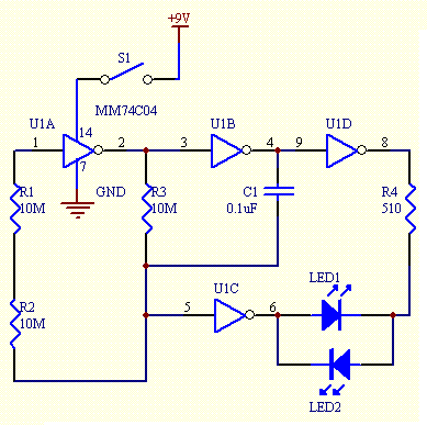
This simple LED light flasher project utilizes a Hex Inverter 74C04 integrated circuit (IC) to generate a square wave pulse, which is employed to alternately turn two LEDs on and off.
The circuit design comprises a 74C04 Hex Inverter IC, which...

LED Hat
This unique hat is a product of a procrastination project. During the study break for final exams, an invitation was received for a friend's hat-themed birthday party. With little else to occupy time (aside from studying), the decision was made...

12v led lamp circuit
This project involves a 12V LED lamp circuit that is notably simple. The circuit comprises five resistors and fifteen super bright white 5mm LEDs, which are readily available at low prices. It is compatible with any type of 12-volt battery,...

LED audio peak level
A peak level indicator when a signal exceeds a certain maximum value. It can be quite useful, for instance, with tape recorders, mixing consoles etc. One of the most important requirements of a peak level indicator is that it should...

Using AC for LED Christmas Lights
This circuit utilizes low-voltage AC to power a string of approximately 50 bi-color LEDs, with two LEDs connected in inverse parallel. The power supplied to the LEDs is managed by a Triac and two optocouplers, whose phototransistors are also connected...

Simple 100W inverter schematic design
This document provides an explanation of a simple 100-watt inverter circuit using the IC CD4047 and the IRF540 MOSFET. The circuit is designed to be simple, cost-effective, and suitable for assembly on a veroboard. The CD4047 is a low-power CMOS...

12 to 120 Volt Inverter
It will supply 15 watts of AC power to a device. It should power lamps, shavers, small stereos and small appliances. If you draw too much power the circuit will shut down all by itself. The output of this circuit...