


60W-flashing-light
#flashing light
#transistor
#2N6101
#heatsink
#resistor
#adjustable
#60W
#light control
#circuit design

Description: The 2N6101 transistor should be mounted on a small heatsink. The 300 kΩ resistor controls the off period and might need to be adjusted if the transistor gains are high. The 100 kΩ resistor controls the on period.
The 2N6101 is a power transistor that requires effective thermal management due to its potential heat generation during operation. Mounting it on a small heatsink is essential to maintain its junction temperature within safe limits, thereby ensuring reliability and performance. The heatsink should be selected based on the expected power dissipation and the ambient temperature of the operating environment.
In the circuit configuration, a 300 kΩ resistor is utilized to manage the off period of the transistor. This resistor is critical in determining the duration for which the transistor remains in the non-conducting state. If the gain of the transistor is high, it may lead to an increased turn-off time, necessitating adjustments to the resistor value to achieve the desired timing characteristics. This adjustment is crucial for applications requiring precise control over switching times.
Additionally, a 100 kΩ resistor is employed to control the on period of the transistor. This resistor influences the time the transistor spends in the conducting state. The value of this resistor can be adjusted to tailor the on duration according to the specific requirements of the application, ensuring optimal performance and efficiency in the circuit.
Overall, careful selection and adjustment of these resistors are vital in ensuring the 2N6101 transistor operates effectively within its intended application, balancing the on and off periods while managing thermal conditions through appropriate heatsinking.The 2N6101 transistor should be mounted on a small heatsink. The 300-KO resistor controls tbe off period and might need to be adjusted if transistor gains are high. The 100-KO resistor controls the on period.
The 2N6101 is a power transistor that requires effective thermal management due to its potential heat generation during operation. Mounting it on a small heatsink is essential to maintain its junction temperature within safe limits, thereby ensuring reliability and performance. The heatsink should be selected based on the expected power dissipation and the ambient temperature of the operating environment.
In the circuit configuration, a 300 kΩ resistor is utilized to manage the off period of the transistor. This resistor is critical in determining the duration for which the transistor remains in the non-conducting state. If the gain of the transistor is high, it may lead to an increased turn-off time, necessitating adjustments to the resistor value to achieve the desired timing characteristics. This adjustment is crucial for applications requiring precise control over switching times.
Additionally, a 100 kΩ resistor is employed to control the on period of the transistor. This resistor influences the time the transistor spends in the conducting state. The value of this resistor can be adjusted to tailor the on duration according to the specific requirements of the application, ensuring optimal performance and efficiency in the circuit.
Overall, careful selection and adjustment of these resistors are vital in ensuring the 2N6101 transistor operates effectively within its intended application, balancing the on and off periods while managing thermal conditions through appropriate heatsinking.The 2N6101 transistor should be mounted on a small heatsink. The 300-KO resistor controls tbe off period and might need to be adjusted if transistor gains are high. The 100-KO resistor controls the on period.

Power Control
The circuit presented utilizes a two-transistor "flasher" to generate triggering pulses, replacing the traditional unijunction transistor design. This configuration allows for a broad range of control with minimal hysteresis and sensitivity to line voltage. Two diodes rectify the line voltage,...

Transistor time relay circuit
This circuit consists of five transistor time relay circuits designed for time relay exchange. It utilizes two different power supplies, maintaining the same circuit configuration. The delay time can be adjusted by modifying a potentiometer. The parameters for the time...
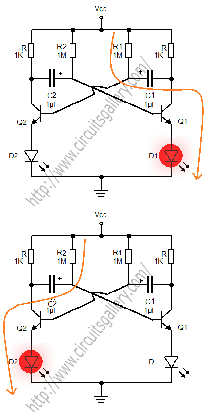
Astable Multivibrator
A transistorized astable multivibrator is a cross-coupled transistor network capable of generating a continuous square wave. It operates as a free-running oscillator or a regenerative switching circuit that utilizes positive feedback. The astable multivibrator continuously alternates between its two unstable...

Motor time division control circuit composed of transistor and NE555
Figure 2-32 (a) illustrates the time control diagram for a motor operated by switch S1. When S1 is set to position 1, the power driver circuit supplies current to the motor, enabling it to run. When S1 is switched to...

Wilf Rigter`s SIMD1 V2
In the never-ending quest for simplicity, even one extra diode is a price I loathe to pay. To avoid using extra components, it struck me that the two diodes in SIMD1 V1 were connected like the two junctions in one...

portable mic pre amp 2 transistor
Portable microphone preamplifier using two transistors, BC549C and BC547B. The electret condenser microphone or microphone's dynamic range is very sensitive.
The portable microphone preamplifier circuit utilizes two transistors, BC549C and BC547B, to amplify the low-level audio signals from an electret condenser...

Metal Detector Circuit with Diagram and Schematic
A simple metal detector circuit diagram and schematic using a single transistor and a radio. This metal detector/sensor project is easy to make and is an application of a Colpitts oscillator.
The metal detector circuit utilizes a single transistor in conjunction...

wireless fm transmitter
The wireless transmitter circuit utilizes transistor T1 (BF494) as a low-power variable-frequency VHF oscillator. A varicap diode circuit is incorporated to modify the frequency of the FM transmitter and to facilitate frequency modulation using audio signals. The output power of...

Touch-on-off-electronic-switch
Transistors Q1 and Q2 control latches Q3 and Q4 to switch on the lamp. A high resistance from touching the electrode biases Q1 or Q2 on, setting or resetting the latch.
In this circuit, transistors Q1 and Q2 function as input...