


A plurality of sets of three loop flashing lights chain circuits
#flashing lights
#LED
#220V
#half-wave rectifier
#thyristor
#capacitor
#mains
#chain circuit
#synchronization

Description: The circuit operates with a 220V mains supply through a diode (VDi) configured as a half-wave rectifier. Capacitors C1 to C3 are charged, and due to the lack of full synchronization in the charging process, a pilot thyristor is required to control the lighting of a lantern. This setup allows for three sets of lights (EL1 to EL3) to alternate between being illuminated and extinguished.
The described circuit utilizes a half-wave rectifier configuration, where the diode (VDi) allows current to flow only during one half of the AC cycle, effectively converting the AC voltage to a pulsating DC voltage. This rectified output is then used to charge capacitors C1, C2, and C3. These capacitors serve as energy storage elements, smoothing the output voltage to some extent but not completely eliminating the ripple due to the nature of half-wave rectification.
The pilot thyristor plays a crucial role in managing the illumination of the lantern. When the voltage across the capacitors reaches a certain threshold, the thyristor is triggered, allowing current to flow through the lantern, thus illuminating it. The thyristor remains conductive until the current flowing through it falls below a certain level, at which point it turns off, allowing the lantern to extinguish. This on-off switching creates a visual effect where the three sets of lights (EL1, EL2, and EL3) alternate in brightness.
The alternating illumination of the lights can be achieved by connecting each light set to a different timing circuit or by employing a control mechanism that sequentially triggers the thyristor at specific intervals. This creates a visually appealing effect, often used in decorative lighting applications. Proper component selection, including the ratings of the diode, capacitors, and thyristor, is essential to ensure the reliability and safety of the circuit when operating at mains voltage. Additionally, consideration should be given to the thermal management of the components, especially the thyristor, due to the potential for heat generation during operation.220V mains via diode VDi half-wave rectifier, the capacitor Cl-C3 charge, since the charge is not fully synchronized, so there must be a pilot thyristor through, lit lantern in the group, so three sets of lights ELi ~ EL3 rotation point bright and extinguished.
The described circuit utilizes a half-wave rectifier configuration, where the diode (VDi) allows current to flow only during one half of the AC cycle, effectively converting the AC voltage to a pulsating DC voltage. This rectified output is then used to charge capacitors C1, C2, and C3. These capacitors serve as energy storage elements, smoothing the output voltage to some extent but not completely eliminating the ripple due to the nature of half-wave rectification.
The pilot thyristor plays a crucial role in managing the illumination of the lantern. When the voltage across the capacitors reaches a certain threshold, the thyristor is triggered, allowing current to flow through the lantern, thus illuminating it. The thyristor remains conductive until the current flowing through it falls below a certain level, at which point it turns off, allowing the lantern to extinguish. This on-off switching creates a visual effect where the three sets of lights (EL1, EL2, and EL3) alternate in brightness.
The alternating illumination of the lights can be achieved by connecting each light set to a different timing circuit or by employing a control mechanism that sequentially triggers the thyristor at specific intervals. This creates a visually appealing effect, often used in decorative lighting applications. Proper component selection, including the ratings of the diode, capacitors, and thyristor, is essential to ensure the reliability and safety of the circuit when operating at mains voltage. Additionally, consideration should be given to the thermal management of the components, especially the thyristor, due to the potential for heat generation during operation.220V mains via diode VDi half-wave rectifier, the capacitor Cl-C3 charge, since the charge is not fully synchronized, so there must be a pilot thyristor through, lit lantern in the group, so three sets of lights ELi ~ EL3 rotation point bright and extinguished.

LED Flashing circuits
This is a very simple project using a printed circuit board and 8 components. It will flash an ordinary 3mm or 5mm (1/8" or 1/4") LED at a rate of about one flash per second. This circuit works on the...

making led flash every 0 6 seconds
A question about electronics involves a project to create a simple circuit that causes an LED to flash.
To design a circuit that makes an LED flash, a basic understanding of electronic components and their configurations is essential. The simplest method...

Light Chaser Ii
Up to six lights can be sequentially flashed using this circuit. LED1 through LED6 can be replaced by optocouplers (MOC3010, etc.) to control 120-Vac loads via triacs. Ul generates pulses that clock the shift register mode of the six D...

A semi-practical capacitor-powered flashlight
High-energy capacitors can produce hundreds of amps when short-circuited, potentially causing severe burns, fires, and property damage. It is essential to be aware of these hazards when using such capacitors and to take precautions to avoid accidental short-circuits. The capacitor-powered...

Resistive-Capacitive sinusoidal synchronous reset control transistor trigger circuit
The circuit is designed for inductive loads, specifically within a thyristor power unit, such as a three-phase step-down DC motor speed control and other applications. It is capable of delivering sufficient output power to trigger a thyristor rated at 100A....

Electronic Birthday Candle
The concept involves mounting a microphone on a stick with an LED and designing a circuit that responds to loud noises detected by the microphone input (such as blowing) to turn off the LED. The schematic is straightforward, powered by...
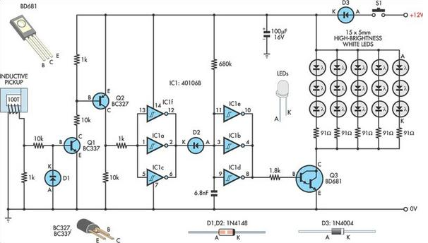
Automotive LED Timing Light
A useful timing strobe can be constructed using high-brightness LEDs and a few common components. Ignition pulses from the number 1 cylinder high-tension lead are used to trigger the circuit via a homemade inductive pickup. Transistors Q1 and Q2 buffer...

1A Low Noise High Current LED Torch/Flash
An ultralow dropout current source maintains accurate LED current at very low ILED voltages. Automatic mode switching optimizes efficiency by monitoring the voltage across the LED current source and switching modes only when ILED dropout is detected. The LTC3216 is...

Phase protective circuit of harmonic currents 2 b
Both circuits are used to control the thyristor contactor KM action to overcome the break phase protection relay prone to malfunction or refuse to move, and enhance the sensitivity and reliability of the protection device.
The described circuits are designed to...