


AC line circuit diagram of photoelectric switch

Description: The circuit is designed to activate when the light intensity exceeds 700lx. In this configuration, a phototransistor and the BFY52 transistor are used to trigger the BTY91 thyristor with a current. When light strikes the phototransistor, a positive trigger pulse is generated approximately every 6 degrees after the initial activation. The average load current flowing through the half-wave DC circuit can reach up to 16A. The BZY88/C5 regulator, along with transistor T1 and a 390-ohm resistor, is employed to ensure that the trigger circuit voltage does not exceed 6V. A BYX45 diode is included to block the negative half-cycle of the grid voltage, while additional resistors and a 0.1uF capacitor are used to protect the thyristor from overvoltage conditions.
The circuit operates based on light intensity detection, utilizing a phototransistor as the primary sensing element. When ambient light levels rise above the specified threshold of 700lx, the phototransistor conducts, allowing current to flow and activating the BFY52 transistor. This transistor, in turn, generates a trigger pulse that is sent to the BTY91 thyristor, which is responsible for controlling the load current. The thyristor can handle significant current levels, up to 16A, making it suitable for various applications requiring high power.
The BZY88/C5 voltage regulator serves a critical role in maintaining the stability of the trigger circuit. It ensures that the voltage remains within safe limits, specifically below 6V, which is essential for the reliable operation of the components involved. The inclusion of a 390-ohm resistor helps to limit the current flowing into the trigger circuit, further protecting sensitive components from potential damage due to excessive voltage or current.
To prevent damage from negative voltage spikes, a BYX45 diode is positioned in the circuit to block any negative half-cycles from the AC supply. This diode ensures that only the positive half of the waveform contributes to the circuit's operation, which is crucial for maintaining the functionality of the thyristor.
Additionally, the circuit includes protective elements such as resistors and a 0.1uF capacitor that work together to mitigate overvoltage risks. These components help to absorb any transient voltage spikes that could occur during operation, thereby enhancing the overall reliability and longevity of the circuit.
In summary, this circuit is a sophisticated arrangement that leverages light intensity detection to control high-current loads safely and effectively. The careful selection of components and their arrangement ensures that the system operates reliably while providing necessary protections against voltage fluctuations.As shown in the circuit to light when the intensity 700lx above action, this time through the phototransistor and the transistor BFY52 BPX25 to thyristor BTY91 / 800R trigger current. When the light is irradiated on the phototransistor, the trigger pulse is always in the positive half weeks after the starting point occurred about 6 degrees each, by the arithmetic mean of the load flows through the half-wave DC current up to 16A. Regulator BZY88 / C5 and transistor T1 and the resistor 390 is connected to Europe, for limiting the trigger circuit voltage does not exceed 6V.
Diode BYX45 / 800R for blocking the negative half-cycle grid voltage, resistors and capacitors 0.1uF 33 Europe for protecting thyristors against overvoltage.
The circuit operates based on light intensity detection, utilizing a phototransistor as the primary sensing element. When ambient light levels rise above the specified threshold of 700lx, the phototransistor conducts, allowing current to flow and activating the BFY52 transistor. This transistor, in turn, generates a trigger pulse that is sent to the BTY91 thyristor, which is responsible for controlling the load current. The thyristor can handle significant current levels, up to 16A, making it suitable for various applications requiring high power.
The BZY88/C5 voltage regulator serves a critical role in maintaining the stability of the trigger circuit. It ensures that the voltage remains within safe limits, specifically below 6V, which is essential for the reliable operation of the components involved. The inclusion of a 390-ohm resistor helps to limit the current flowing into the trigger circuit, further protecting sensitive components from potential damage due to excessive voltage or current.
To prevent damage from negative voltage spikes, a BYX45 diode is positioned in the circuit to block any negative half-cycles from the AC supply. This diode ensures that only the positive half of the waveform contributes to the circuit's operation, which is crucial for maintaining the functionality of the thyristor.
Additionally, the circuit includes protective elements such as resistors and a 0.1uF capacitor that work together to mitigate overvoltage risks. These components help to absorb any transient voltage spikes that could occur during operation, thereby enhancing the overall reliability and longevity of the circuit.
In summary, this circuit is a sophisticated arrangement that leverages light intensity detection to control high-current loads safely and effectively. The careful selection of components and their arrangement ensures that the system operates reliably while providing necessary protections against voltage fluctuations.As shown in the circuit to light when the intensity 700lx above action, this time through the phototransistor and the transistor BFY52 BPX25 to thyristor BTY91 / 800R trigger current. When the light is irradiated on the phototransistor, the trigger pulse is always in the positive half weeks after the starting point occurred about 6 degrees each, by the arithmetic mean of the load flows through the half-wave DC current up to 16A. Regulator BZY88 / C5 and transistor T1 and the resistor 390 is connected to Europe, for limiting the trigger circuit voltage does not exceed 6V.
Diode BYX45 / 800R for blocking the negative half-cycle grid voltage, resistors and capacitors 0.1uF 33 Europe for protecting thyristors against overvoltage.
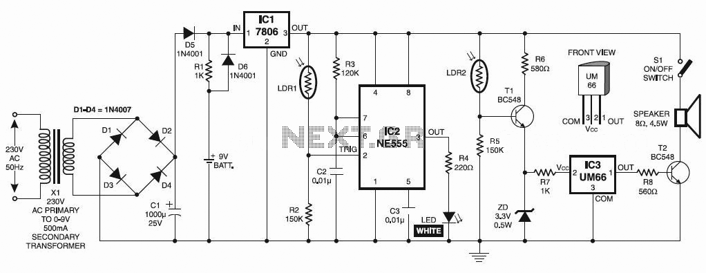
Automatic Night Lamp with Morning Alarm
This circuit automatically activates a night lamp when the bedroom light is turned off. The lamp stays illuminated until the light sensor detects daylight in the morning. A super-bright white LED is utilized as the night lamp, providing bright and...

Automatic Light Switch Circuit
This light-sensitive automatic light switch circuit is designed to be connected to the main 220V supply. The circuit will activate a 220V lamp during nighttime.
The light-sensitive automatic light switch circuit operates by utilizing a light-dependent resistor (LDR) to detect ambient...
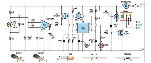
Super Light Sensor
This Super Light Sensor responds to minute fluctuations in light levels, automatically adjusting from approximately 200 lux to 60,000 lux (from a modestly lit room to direct sunlight). It has various potential applications, such as detecting a car entering a...

light sensor circuit
This is a light sensor circuit designed to detect light and activate a relay. The circuit is straightforward and requires only a few components. The operation of the circuit is simple: when the photoresistor detects light, it will turn on...

Light-Controlled Pond Pump
This circuit was designed to automatically control a garden pond pump, turning it on at dawn and off at dusk. This automation eliminates the need for manual operation, particularly beneficial during holidays when the owners are away. The controller derives...
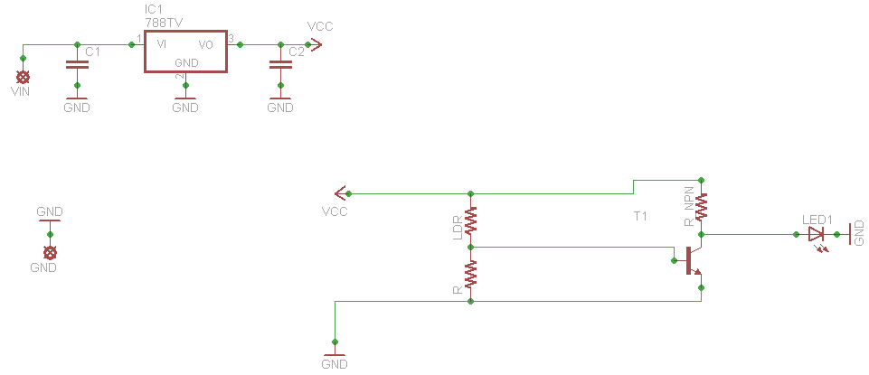
light sensor
When connecting this element in a voltage divider configuration, a high and low signal can be generated based on the amount of light detected by the sensor. An NPN transistor configured as an inverter further filters this signal to produce...

6V Light Barrier Sensor Detector
The following circuit illustrates a Light Barrier Sensor Detector Circuit Diagram. Features include a single transistor, an adjustable potentiometer, and a 6V power supply.
The Light Barrier Sensor Detector Circuit is designed to detect the presence of an object by utilizing...

Light beam operated on-off relay
When a beam of light strikes the photocell, the voltage across the neon lamp NE-1 rises sharply. NE-1 turns on and triggers the SCR. K1 is an impulse relay whose contacts remain in position even after the coil current is...

Light Sensitive trigger
All components have been placed on the PCB, but there is uncertainty regarding the connection of the power and load in relation to the relays.
The integration of relays into a printed circuit board (PCB) design requires a clear understanding of...