


Automatic Dual output Bulb Display
#bulb display
#sequential lighting
#oscillator
#BCD counter
#CD4510
#CD4017
#toggle flip-flop
#visual effect
#automatic control

Description: This circuit lights up ten bulbs sequentially, first in one direction and then in the opposite direction, thus presenting a nice visual effect. In this circuit, gates N1 and N2 form an oscillator. The output of this oscillator is used as a clock for BCD up/down counter CD4510 (IC2). Depending on the logic state at its pin 10, the counter counts up or down. During count up operation, pin 7 of IC2 outputs an active low pulse on reaching the ninth count. Similarly, during count-down operation, you again get a low-going pulse at pin 7. This terminal count output from pin 7, after inversion by gate N3, is connected to clock pin 14 of decade counter IC3 (CD4017) which is configured here as a toggle flip-flop by returning its Q2 output at pin 4 to reset pin 15. Thus output at pin 3 of IC3 goes to logic 1 and logic 0 state alternately at each terminal count of IC2. Initially, pin 3 (Q0) of IC3 is high and the counter is in count-up state. On reaching ninth count, pin 3 of IC3 goes low and as a result IC2 starts counting down. When the counter reaches 0 count, Q2 output of IC3 momentarily goes high to reset it, thus taking pin 3 to logic 1 state, and the cycle repeats. The BCD output of IC2 is connected to 1-of-10 decoder CD4028 (IC4). During count-up operation of IC2, the outputs of IC4 go logic high sequentially from Q0 to Q9 and thus trigger the triacs and lighting bulbs 1 through 10, one after the other. Thereafter, during count-down operation of IC2, the bulbs light in the reverse order, presenting a wonderful visual effect.
This circuit employs a combination of digital and analog components to achieve a visually appealing sequential lighting effect using ten bulbs. The heart of the system consists of two main integrated circuits: the CD4510 BCD up/down counter (IC2) and the CD4017 decade counter (IC3). The CD4510 counter operates as a BCD counter, allowing it to count from 0 to 9 and then back down to 0, while its output is used to control the sequence of the bulbs.
The oscillator formed by gates N1 and N2 provides a clock signal to IC2, enabling it to increment or decrement based on the logic level present at pin 10. The count direction is determined by this input, allowing for dynamic control over the counting process. The output at pin 7 of IC2 is crucial, as it generates a low pulse upon reaching the ninth count, signaling IC3 to toggle its output state.
The CD4017 decade counter is configured as a toggle flip-flop through the feedback from its Q2 output to the reset pin. This configuration ensures that the output at pin 3 of IC3 alternates between high and low states, effectively creating a binary count that corresponds to the counting operation of IC2. When IC2 counts up and reaches nine, IC3's output transitions, prompting IC2 to count down. This cyclical behavior produces a continuous sequence of lighting effects.
The CD4028 one-of-ten decoder (IC4) translates the BCD output from IC2 into a format suitable for driving the bulbs. Each output from IC4 corresponds to a specific bulb, and as IC2 counts up, the outputs sequentially activate triacs that control the power to the bulbs. This process is mirrored in reverse during the countdown operation, which creates an engaging visual display as the bulbs light up in a sequential pattern both forwards and backwards.
Overall, this circuit exemplifies the integration of digital logic and power control components to create an effective and visually stimulating lighting sequence.This circuit lights up ten bulbs sequentially, first in one direc- tion and then in the opposite direction, thus presenting a nice visual effect. In this circuit, gates N1 and N2 form an oscillator. The output of this oscillator is used as a clock for BCD up/down counter CD4510 (IC2). Depending on the logic state at its pin 10, the counter counts up or down. During count up operation, pin 7 of IC2 outputs an active low pulse on reaching the ninth count. Similarly, during count-down operation, you again get a low-going pulse at pin 7. This terminal count output from pin 7, after inversion by gate N3, is connected to clock pin 14 of decade counter IC3 (CD4017) which is configured here as a toggle flip-flop by returning its Q2 output at pin 4 to reset pin 15.
Thus output at pin 3 of IC3 goes to logic 1 and logic 0 state alternately at each terminal count of IC2. Initially, pin 3 (Q0) of IC3 is high and the counter is in count-up state. On reaching ninth count, pin 3 of IC3 goes low and as a result IC2 starts counting down. When the counter reaches 0 count, Q2 output of IC3 momentarily goes high to reset it, thus taking pin 3 to logic 1 state, and the cycle repeats.
The BCD output of IC2 is connected to 1-of-10 decoder CD4028 (IC4). During count-up operation of IC2, the outputs of IC4 go logic high sequentially from Q0 to Q9 and thus trigger the triacs and lighting bulbs 1 through 10, one after the other. Thereafter, during count-down operation of IC2, the bulbs light in the reverse order, presenting a wonderful visual effect.
This circuit employs a combination of digital and analog components to achieve a visually appealing sequential lighting effect using ten bulbs. The heart of the system consists of two main integrated circuits: the CD4510 BCD up/down counter (IC2) and the CD4017 decade counter (IC3). The CD4510 counter operates as a BCD counter, allowing it to count from 0 to 9 and then back down to 0, while its output is used to control the sequence of the bulbs.
The oscillator formed by gates N1 and N2 provides a clock signal to IC2, enabling it to increment or decrement based on the logic level present at pin 10. The count direction is determined by this input, allowing for dynamic control over the counting process. The output at pin 7 of IC2 is crucial, as it generates a low pulse upon reaching the ninth count, signaling IC3 to toggle its output state.
The CD4017 decade counter is configured as a toggle flip-flop through the feedback from its Q2 output to the reset pin. This configuration ensures that the output at pin 3 of IC3 alternates between high and low states, effectively creating a binary count that corresponds to the counting operation of IC2. When IC2 counts up and reaches nine, IC3's output transitions, prompting IC2 to count down. This cyclical behavior produces a continuous sequence of lighting effects.
The CD4028 one-of-ten decoder (IC4) translates the BCD output from IC2 into a format suitable for driving the bulbs. Each output from IC4 corresponds to a specific bulb, and as IC2 counts up, the outputs sequentially activate triacs that control the power to the bulbs. This process is mirrored in reverse during the countdown operation, which creates an engaging visual display as the bulbs light up in a sequential pattern both forwards and backwards.
Overall, this circuit exemplifies the integration of digital logic and power control components to create an effective and visually stimulating lighting sequence.This circuit lights up ten bulbs sequentially, first in one direc- tion and then in the opposite direction, thus presenting a nice visual effect. In this circuit, gates N1 and N2 form an oscillator. The output of this oscillator is used as a clock for BCD up/down counter CD4510 (IC2). Depending on the logic state at its pin 10, the counter counts up or down. During count up operation, pin 7 of IC2 outputs an active low pulse on reaching the ninth count. Similarly, during count-down operation, you again get a low-going pulse at pin 7. This terminal count output from pin 7, after inversion by gate N3, is connected to clock pin 14 of decade counter IC3 (CD4017) which is configured here as a toggle flip-flop by returning its Q2 output at pin 4 to reset pin 15.
Thus output at pin 3 of IC3 goes to logic 1 and logic 0 state alternately at each terminal count of IC2. Initially, pin 3 (Q0) of IC3 is high and the counter is in count-up state. On reaching ninth count, pin 3 of IC3 goes low and as a result IC2 starts counting down. When the counter reaches 0 count, Q2 output of IC3 momentarily goes high to reset it, thus taking pin 3 to logic 1 state, and the cycle repeats.
The BCD output of IC2 is connected to 1-of-10 decoder CD4028 (IC4). During count-up operation of IC2, the outputs of IC4 go logic high sequentially from Q0 to Q9 and thus trigger the triacs and lighting bulbs 1 through 10, one after the other. Thereafter, during count-down operation of IC2, the bulbs light in the reverse order, presenting a wonderful visual effect.

High-current-oscillator
The oscillator output of the XR-567 can be amplified using the output amplifier and high-current logic output available at pin 8. In this manner, the circuit can switch 100-mA load currents without sacrificing oscillator stability. The oscillator frequency can be...

Clap Activated Remote With CD4017 IC
The disadvantage of infrared or wireless remote control is that the remote transmitter is often misplaced. This circuit design offers a way to control ...
This circuit design addresses the common issue of misplaced remote transmitters in infrared or wireless remote...

LC CHECKER
The circuit operates on the principle of the grid-dip or absorption effect, which takes place when a parallel resonant circuit is coupled to an oscillator operating at the same frequency. Transistor Q1 functions within a standard Colpitts oscillator circuit, maintaining...

Marker-generator
The oscillator section employs three sections of a 7400 quad NAND gate integrated circuit. The 1 MHz signal generated by the oscillator is input into a 7490 decade counter, which is configured to divide by ten, producing a 100 kHz...

VHF/UHF TV Modulator
A simple oscillator generates a frequency in the VHF or UHF range. This oscillator is modulated with a video signal, and the resulting modulated carrier wave is transmitted to the TV set's aerial input through a cable. The final step...

Metal detector circuit diagram 6
The metal detector circuit consists of several key components including the probe oscillator, reference oscillator, oscillation signal processor, mixing amplifier, and ammeter PA. The probe oscillator is made up of the oscillating tube VI, exploration coil L1, capacitors C1 to...

ring bell electronic circuit
This circuit generates an oscillating frequency of approximately 1 kHz, which can be adjusted by changing the value of resistor R1. The speaker will emit a continuous beep sound at this frequency.
The circuit utilizes a basic oscillator configuration, likely...
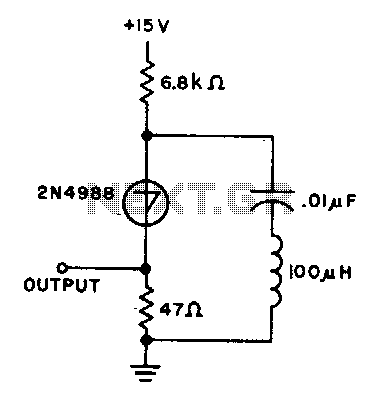
10Khz oscillator
The capacitor charges until the switching voltage is reached. When the switch (SUS) is activated, the inductor causes the current to oscillate. When the current through the switch drops below the holding current, the device turns off, and the cycle...

Do Oscillation Building Circuit by Your Self!
An oscillator is a mechanical or electronic device that operates based on the principles of oscillation. Oscillators serve as fundamental building blocks upon which the entire structure of electronics and computers is established. An article is available that explains how...