


Automatic multipurpose emergency lights circuit diagram
#emergency lights
#automatic switching
#power failure
#battery backup
#LED
#mains power
#standby mode
#energy efficient
#home automation
#safety

Description: An automatic multipurpose emergency lights circuit is presented. Typically, emergency lights are connected to the mains for standby when fully charged. In the event of a sudden power failure, the ambient light transitions from strong to weak, indicating a smart detection of darkness due to power outages. The emergency lights activate promptly. After 10 minutes, the emergency lights will automatically turn off, as the general staff will have been evacuated to a safe location, eliminating the need for continued lighting. This automatic shutdown helps prevent excessive discharge of lead-acid batteries, thereby reducing the risk of damage.
The automatic multipurpose emergency light circuit is designed to provide reliable illumination during power outages while ensuring the longevity of the battery system. The circuit typically consists of several key components: a power supply unit, a battery management system, a light sensor, a microcontroller, and LED light sources.
The power supply unit is connected to the mains, allowing the circuit to charge the lead-acid batteries during normal operation. The battery management system monitors the state of charge of the batteries, ensuring they remain within safe operating limits. This system is crucial for maintaining battery health and preventing over-discharge.
A light sensor is incorporated into the circuit to detect ambient light levels. When the sensor detects a drop in light intensity, indicating a power failure, it sends a signal to the microcontroller. The microcontroller then activates the LED light sources, providing immediate illumination to the area. The circuit is programmed to keep the lights on for a preset duration, typically 10 minutes, after which it automatically turns off the lights to conserve battery power.
This feature is particularly important in emergency situations, where prolonged illumination is not necessary once personnel have evacuated to safety. The automatic shutdown mechanism helps prevent the batteries from entering a deep discharge state, which could lead to permanent damage.
Overall, the design of this emergency light circuit prioritizes functionality, safety, and efficiency, making it an essential component for any facility's emergency preparedness plan. Automatic multipurpose emergency lights circuit is shown. Usually emergency lights connected to the mains, in fully charged standby. When a sudden power failure and sudden ambi ent light from strong to weak when it is determined that this is a smart dark due to the power outages caused by lit and timely emergency lights. After 10min After the emergency light will automatically turn off, then the general staff had been evacuated to a safe location, no longer need to provide lighting, emergency lights can be turned off to prevent further damage to the excessive discharge of lead-acid batteries.
The automatic multipurpose emergency light circuit is designed to provide reliable illumination during power outages while ensuring the longevity of the battery system. The circuit typically consists of several key components: a power supply unit, a battery management system, a light sensor, a microcontroller, and LED light sources.
The power supply unit is connected to the mains, allowing the circuit to charge the lead-acid batteries during normal operation. The battery management system monitors the state of charge of the batteries, ensuring they remain within safe operating limits. This system is crucial for maintaining battery health and preventing over-discharge.
A light sensor is incorporated into the circuit to detect ambient light levels. When the sensor detects a drop in light intensity, indicating a power failure, it sends a signal to the microcontroller. The microcontroller then activates the LED light sources, providing immediate illumination to the area. The circuit is programmed to keep the lights on for a preset duration, typically 10 minutes, after which it automatically turns off the lights to conserve battery power.
This feature is particularly important in emergency situations, where prolonged illumination is not necessary once personnel have evacuated to safety. The automatic shutdown mechanism helps prevent the batteries from entering a deep discharge state, which could lead to permanent damage.
Overall, the design of this emergency light circuit prioritizes functionality, safety, and efficiency, making it an essential component for any facility's emergency preparedness plan. Automatic multipurpose emergency lights circuit is shown. Usually emergency lights connected to the mains, in fully charged standby. When a sudden power failure and sudden ambi ent light from strong to weak when it is determined that this is a smart dark due to the power outages caused by lit and timely emergency lights. After 10min After the emergency light will automatically turn off, then the general staff had been evacuated to a safe location, no longer need to provide lighting, emergency lights can be turned off to prevent further damage to the excessive discharge of lead-acid batteries.
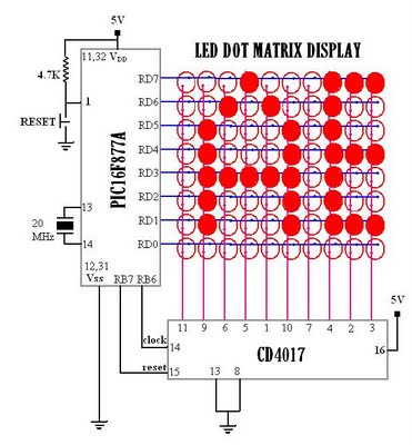
Scrolling text in LED dotmatrix display
Multiplexed displays are electronic displays where the entire display is not driven simultaneously. Instead, sub-units of the display—typically rows or columns for a dot matrix display or individual characters for a character-oriented display—are multiplexed. This means that they are driven...

White LEDs Flashlight
Here is a schematic of a rechargeable 9-LED flashlight using two Gates SLA cells and nine LEDs. It is as bright as when the single bulb was used, and lasts 3 times longer per charge. That is about 10 hours...

Low Cost Automatic LED Emergency Light
This is a low-cost circuit diagram for an emergency light utilizing a white LED. Components include an LM317 IC, a resistor, a transformer, an LED, and a variable resistor.
The emergency light circuit using a white LED is designed for efficiency...

Power Resumption Alarm circuit
This is a simple power resumption alarm circuit that can be installed within the switch box. It emits beeping sounds when power is restored following a power failure.
The power resumption alarm circuit is designed to provide an audible alert upon...

Multicolor HD LED
Most PC enclosures provide only a single LED to indicate hard disk access, with the LED being connected to the motherboard via a two-pin connector. However, this LED only works with IDE drives, and if a SCSI disk controller is...

A passive light emitting diode output level indication circuit
A passive light-emitting diode output level indication circuit.
This circuit utilizes a light-emitting diode (LED) to provide a visual indication of the output level from a given source. The design is characterized by its passive nature, meaning it does not require...

LED pulse width modulator
Early in the exploration of high-power LEDs, such as the Luxeon 1 and 3-watt devices, the potential of Pulse Width Modulation (PWM) techniques for LED modulation was considered. This method theoretically minimizes distortion by making the LED's "Current versus Luminous...

LED effects with ATTYNI2313
This project I made for my little daughter. It is 24 channel light illumination. The schematic is very simple 24 LEDs, 1 MCU and some additional components. The main principle is dynamic indication, which is usually implemented for control of...

Light emitting diode circuit of the temperature control
The circuit consists of two light-emitting diodes (D1 and D2) whose operation is controlled by the ambient temperature. A temperature sensor, the LM35, generates an output of 10 mV for each degree of temperature increase. A reference potentiometer, R2, is...