


Blackout emergency lights 4
#emergency lights
#transformer
#rectifier
#battery charger
#AC to DC
#power supply
#220V
#smoothing filter
#diode
#blackout

Description: The charging circuit comprises a transformer (Tl), diodes (VDI-VD4), and various additional components. It operates on 220V AC, with the transformer Tl stepping down the voltage, while diodes VDI-VD4 perform rectification. A smoothing filter (CI) converts the rectified output into DC power suitable for charging a battery. A function selector switch (G) indicates the charging state, allowing the user to monitor the battery's charge level. When the DC voltage charges the battery through a resistor (Rl), an LED indicator illuminates. Once the battery reaches a sufficient charge, the charging current decreases, resulting in a reduced voltage drop across Rl, which eventually turns off the LED, signaling that the battery is fully charged. Additionally, when the switch is set to the emergency lighting mode, a triode (VT) and a boosting transformer coil (L1, L2) along with capacitors (C3-C5) form an inductance feedback oscillator. This oscillator generates an oscillating voltage that is applied to a boost coil (L3), which powers fluorescent tubes (H) for illumination. When the switch is in position 2, the circuit is turned off.
The charging circuit is designed to efficiently convert AC mains voltage into a usable DC voltage for battery charging applications. The transformer Tl steps down the high-voltage AC input to a lower AC voltage, which is then rectified by diodes VDI-VD4 to produce a pulsating DC voltage. The smoothing filter (CI) typically consists of capacitors that help to flatten the pulsating DC output, ensuring a stable voltage level for the battery charging process.
The function selector switch (G) allows the user to select different operational modes, including a charging mode and an emergency lighting mode. In the charging mode, the resistor (Rl) limits the charging current to prevent overcharging, while the LED indicator provides a visual cue of the charging status. When the battery is sufficiently charged, the LED indicator turns off, indicating that the charging process can be safely terminated.
In emergency lighting mode, the circuit utilizes a feedback oscillator formed by the triode (VT) and transformer coils (L1, L2) along with capacitors (C3-C5). This configuration generates a high-frequency oscillation that is transformed into a higher voltage by the boost coil (L3). The resulting voltage is applied to the fluorescent tubes (H), providing illumination in emergency situations. The design ensures that the circuit can quickly switch between charging and lighting modes, making it versatile for various applications. The overall layout and component selection are critical for achieving efficient operation and reliability in both charging and emergency lighting functionalities. Charging circuit by the transformer Tl, diode VDI-VD4 and other components, 220V AC by Tl buck, VDI ~ VD4 rectification, CI smoothing filter into DC power to charge the battery G provided. S for the function selector switch position shown for the state of charge, when the DC voltage to charge the battery via a resistor Rl G. LED charging indicator light emitting tube, when the reservoir after sufficient battery G, because the charging current is reduced, the voltage drop across Rl also decreases insufficient to maintain the LED has turned on, LED will automatically turn off, indicating that G is fully charged.
When 3:00 s dial switch to the position for the emergency lighting state. Triode VT, 1r2 boosting transformer coil L1, L2 and a capacitor C3 ~ C5 composition inductance feedback oscillator, an oscillating voltage applied directly after the boosted boost coil L3 to fluorescent tubes H both ends of the excitation lamp H light. When the switch to the position 2, is turned off.
The charging circuit is designed to efficiently convert AC mains voltage into a usable DC voltage for battery charging applications. The transformer Tl steps down the high-voltage AC input to a lower AC voltage, which is then rectified by diodes VDI-VD4 to produce a pulsating DC voltage. The smoothing filter (CI) typically consists of capacitors that help to flatten the pulsating DC output, ensuring a stable voltage level for the battery charging process.
The function selector switch (G) allows the user to select different operational modes, including a charging mode and an emergency lighting mode. In the charging mode, the resistor (Rl) limits the charging current to prevent overcharging, while the LED indicator provides a visual cue of the charging status. When the battery is sufficiently charged, the LED indicator turns off, indicating that the charging process can be safely terminated.
In emergency lighting mode, the circuit utilizes a feedback oscillator formed by the triode (VT) and transformer coils (L1, L2) along with capacitors (C3-C5). This configuration generates a high-frequency oscillation that is transformed into a higher voltage by the boost coil (L3). The resulting voltage is applied to the fluorescent tubes (H), providing illumination in emergency situations. The design ensures that the circuit can quickly switch between charging and lighting modes, making it versatile for various applications. The overall layout and component selection are critical for achieving efficient operation and reliability in both charging and emergency lighting functionalities. Charging circuit by the transformer Tl, diode VDI-VD4 and other components, 220V AC by Tl buck, VDI ~ VD4 rectification, CI smoothing filter into DC power to charge the battery G provided. S for the function selector switch position shown for the state of charge, when the DC voltage to charge the battery via a resistor Rl G. LED charging indicator light emitting tube, when the reservoir after sufficient battery G, because the charging current is reduced, the voltage drop across Rl also decreases insufficient to maintain the LED has turned on, LED will automatically turn off, indicating that G is fully charged.
When 3:00 s dial switch to the position for the emergency lighting state. Triode VT, 1r2 boosting transformer coil L1, L2 and a capacitor C3 ~ C5 composition inductance feedback oscillator, an oscillating voltage applied directly after the boosted boost coil L3 to fluorescent tubes H both ends of the excitation lamp H light. When the switch to the position 2, is turned off.

Nicad / NiMh Battery charger
Using this circuit will give good charging results to a sealed lead acid battery, like I use in the metal detector. This circuit is extremely small in size and has a low parts count, making it ideal in some situations....

Car battery charging circuit diagram
The circuit operates on the principle of a transformer, bridge rectifier, and conditioning for battery charging. The charging current can be adjusted to approximately 12V at 100A. For battery charging, a charging rate of 10 hours requires a charging current...

Visible-red-continuous-laser-gun
Q1 and Q2 control the primary windings of transformer T1 using a square wave signal, the frequency of which is determined by the magnetic properties of the transformer. Diodes D1 and D2 serve as base return paths for the feedback...
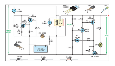
In-Car Charger And Switcher Circuit For SLA Battery
This circuit was designed to control power delivery to a Peltier cooler in a vehicle. The power to the load from the vehicle's battery is managed by a Single Pole Double Throw (SPDT) relay.
The circuit utilizes an SPDT relay to...

Multi-output power supply circuit
This document presents a multi-output power supply circuit. The circuit utilizes the secondary winding of a transformer and incorporates four voltage regulators: 7812, 7805, 7905, and 7912, providing independent output voltages of +12V, +5V, -5V, and -12V, respectively. Each output...

Sony KV-S29MHl TV switching power supply (SIR a 80145A) circuit diagram
The circuit of the Sony KV-S29MHl (S Movement series) TV switching power supply (SIR a 80145A) consists of three main sections: (A) the power oscillation part, (B) the regulator part, and (C) the output section.
The Sony KV-S29MHl TV switching power...

220V 200W Bulb flasher
There is no need to resort to complex circuitry if what you are looking for is a simple power flasher. The light will flash at around 1Hz with a 100W bulb at a duty cycle of 50%. The max. load...

Series DC power supply
A power supply typically consists of a transformer, rectifier, filter, adjustment components, and reference power supply and sampling circuits. Additionally, it may include overload or short circuit protection devices. The circuit begins with a 220V step-down transformer (T) that converts...

Automatic Battery Charger 6V-12V with Relay cut off by LM324
This is an automatic battery charger circuit that utilizes the LM324 integrated circuit, which enhances efficiency. It is capable of charging both 12V and 6V batteries, with filtration managed by switch S1. The circuit is designed to stop charging when...