


Blackout emergency lights circuit 3
#emergency lighting
#blackout
#LED
#controller
#power backup
#automatic switch
#home automation
#energy efficiency

Description: Figure 283 illustrates a blackout emergency lighting controller designed for straightforward external installation with two leads. This controller can directly replace the P Chan Tong Ge opening. Under normal power conditions, it functions like a conventional switch to control lamp E1, turning it off. During a power failure, it activates a small lamp E2 for emergency lighting. The dotted line on the left represents the general lighting circuits, while the right side shows the emergency lighting controller in operation. When the switch S is in the 'on' position, diode VD7 is reverse-biased and turns off lamps E1 and E2.
When power is available, such as from a 220V AC source, current flows through E1, transistor VT1, and diode VD4 for rectification. Diode VD5 conducts, stabilizing the voltage across capacitor C, resulting in a DC voltage of approximately 6V. In this state, the AC voltage allows lamp E1 to illuminate without significantly affecting the brightness of bulb F1. Diode VD7 remains partially closed, keeping lamp E2 lit. The voltage across the terminals is managed by diodes VD3, VD6, and resistor R, charging the battery G.
In the event of a sudden power outage, the energy stored in E1 is released, causing VD5 and VD6 to reverse bias and stop conducting. The battery G, through resistor R, activates diode VD7, which drives the base of transistor VT1, turning it on and powering lamp E2 for emergency lighting. The controller ensures that as long as switch S is open, lamp E2 can function. The power supplied by E1 is regulated to prevent dissipation exceeding 60W, while E2 operates at 3 to 4.8V, suitable for a light bulb. The circuit can utilize four nickel-cadmium or nickel metal hydride batteries in series, with other component parameters specified in the figure, requiring no special requirements.
This emergency lighting controller is designed for reliability and ease of use, ensuring that emergency lighting is available during power outages. The integration of diode rectification and voltage stabilization allows for efficient operation, while the use of rechargeable battery technology supports sustainability. The system is suitable for various applications where emergency lighting is critical, providing a seamless transition from regular to emergency operation without user intervention.FIG. 283 is a blackout emergency lighting controller, it is only the external side in the two lead s, can directly replace P Chan Tong Ge opening, when there is electricity, it can be the same as ordinary switch control lamp 1El light off; a power failure, you can use it controls a small woman E2 bright fire. The figure, the dotted line on the left for the general lighting circuits, power is applied to the right of the emergency lighting controller.
When the switch S button to open the state, because VD7 reverse bias is turned off, lights El, l: 2 are off. When there is electricity, such as switching station r .S 220V AC electricity flow through El, VT) l - a VD4 rectification, then VD5 conduction through steady vs Market, r Liduan capacitance can be formed into a DC voltage of about 6V, in this case AC by vS constitute the old road, put the lamp El Po electroluminescent {star plus voltage across the memory Ej lower than conventional 220V around 6V, this storm will not affect hair too bright bulb F1s degree.
Then VD7 still partial closing beans, so E2 is still light. At the same time, (voltage between both ends by V D3, VD6 and R, G to the battery. If the grid sudden power outage, El grams of electrical energy storage that is put out Rong, VD5, VD6 while reverse bias cut stop, the battery G through R., J-S curse, VD7 cast R, to dig VT1 base transmission, VT1, VT namely conduction, small light E2 powered emergency lighting luminous as if there is no emergency lighting, as long as the open S, E2 can be made to operate lights. lamp power by El regulator vs power dissipation constraints, the power should not exceed belly El 60W.E2 may be 3 8-4.
8V, () light bulb .vs 3A can t {j two L 6V, 1W Zener parallel .G use four nickel-cadmium or nickel metal hydride batteries in series. other component parameters Figure, to no special requirements.
When power is available, such as from a 220V AC source, current flows through E1, transistor VT1, and diode VD4 for rectification. Diode VD5 conducts, stabilizing the voltage across capacitor C, resulting in a DC voltage of approximately 6V. In this state, the AC voltage allows lamp E1 to illuminate without significantly affecting the brightness of bulb F1. Diode VD7 remains partially closed, keeping lamp E2 lit. The voltage across the terminals is managed by diodes VD3, VD6, and resistor R, charging the battery G.
In the event of a sudden power outage, the energy stored in E1 is released, causing VD5 and VD6 to reverse bias and stop conducting. The battery G, through resistor R, activates diode VD7, which drives the base of transistor VT1, turning it on and powering lamp E2 for emergency lighting. The controller ensures that as long as switch S is open, lamp E2 can function. The power supplied by E1 is regulated to prevent dissipation exceeding 60W, while E2 operates at 3 to 4.8V, suitable for a light bulb. The circuit can utilize four nickel-cadmium or nickel metal hydride batteries in series, with other component parameters specified in the figure, requiring no special requirements.
This emergency lighting controller is designed for reliability and ease of use, ensuring that emergency lighting is available during power outages. The integration of diode rectification and voltage stabilization allows for efficient operation, while the use of rechargeable battery technology supports sustainability. The system is suitable for various applications where emergency lighting is critical, providing a seamless transition from regular to emergency operation without user intervention.FIG. 283 is a blackout emergency lighting controller, it is only the external side in the two lead s, can directly replace P Chan Tong Ge opening, when there is electricity, it can be the same as ordinary switch control lamp 1El light off; a power failure, you can use it controls a small woman E2 bright fire. The figure, the dotted line on the left for the general lighting circuits, power is applied to the right of the emergency lighting controller.
When the switch S button to open the state, because VD7 reverse bias is turned off, lights El, l: 2 are off. When there is electricity, such as switching station r .S 220V AC electricity flow through El, VT) l - a VD4 rectification, then VD5 conduction through steady vs Market, r Liduan capacitance can be formed into a DC voltage of about 6V, in this case AC by vS constitute the old road, put the lamp El Po electroluminescent {star plus voltage across the memory Ej lower than conventional 220V around 6V, this storm will not affect hair too bright bulb F1s degree.
Then VD7 still partial closing beans, so E2 is still light. At the same time, (voltage between both ends by V D3, VD6 and R, G to the battery. If the grid sudden power outage, El grams of electrical energy storage that is put out Rong, VD5, VD6 while reverse bias cut stop, the battery G through R., J-S curse, VD7 cast R, to dig VT1 base transmission, VT1, VT namely conduction, small light E2 powered emergency lighting luminous as if there is no emergency lighting, as long as the open S, E2 can be made to operate lights. lamp power by El regulator vs power dissipation constraints, the power should not exceed belly El 60W.E2 may be 3 8-4.
8V, () light bulb .vs 3A can t {j two L 6V, 1W Zener parallel .G use four nickel-cadmium or nickel metal hydride batteries in series. other component parameters Figure, to no special requirements.

Make this Fancy LED Tail Ring Light Circuit for your Car
The following article outlines a sophisticated LED sequencing and diverging ring light that can serve as a tail brake light in vehicles. This circuit concept was proposed by a dedicated reader, Mr. Bobby. The design aims to create a circular...

230V Blinking LED
A pulsating light is used for signaling purposes with a voltage of 230V. A simple circuit has been designed, consisting of an LED diode, two capacitors, two resistors, a diac, and a diode. The operation of the circuit is straightforward....

10 LED VU meter with LM3915
Supply voltage: 12 V. Supply current: 10 mA in stand-by, max. 80 mA. Input voltage: min. 20 mV rms. Indication range: 30 dB. LED currents: 7 mA. Ref. voltage of IC2: 5 V More: R1 - trimmer 100 k mini...

Stress self-test circuit
The circuit operates by utilizing two self-test table contact pads that detect electric pressure changes across the skin. The input voltage is 5 volts, which can drive up to 10 LEDs (the current configuration includes only 5 LEDs). When the...

LED Chaser
I don't know why, but people like blinking lights. You see LED chasers everywhere, in TV shows (Knight Rider), movies, and store windows. This schematic is my version of a simple 10 LED chaser. There is no 555 timer used...

Led-peakmeter
The circuit includes a peak detector that immediately drives the readout to any new higher signal level and slowly lowers it after the signal drops to zero. The readout is a moving dot or expanding bar display. The circuit can...

A passive light emitting diode output level indication circuit
A passive light-emitting diode output level indication circuit.
This circuit utilizes a light-emitting diode (LED) to provide a visual indication of the output level from a given source. The design is characterized by its passive nature, meaning it does not require...

Pocket white-LED torch is power efficient
This single white LED torch can be housed in an empty glue stick tube and has a long rechargeable battery life.
The proposed circuit design features a compact LED torch that utilizes a single white LED as the primary light source....
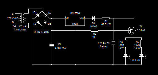
High Bright LED Emergency Lamp
This is a high-efficiency emergency lamp that utilizes high-brightness white LEDs. It automatically activates during power failures and deactivates when power is restored.
The emergency lamp circuit is designed to provide reliable illumination during power outages, utilizing high-brightness white LEDs for...