


CCFL Tester for LCD Screens
#CCFL
#inverter
#LCD backlight
#high voltage
#AC output
#DC input
#fault diagnosis
#electronic testing
#backlight tube
#display repair

Description: The CCFL tube is powered by a small electronic inverter circuit (CCFL inverter) that illuminates the screen electronically. This inverter circuit accepts a low-level DC input voltage and provides a high-level AC output to operate the backlight CCFL tube(s). Often, there is a need to check a faulty LCD backlight circuit to identify dead components. The absence of backlight indicates that either the CCFL inverter or the CCFL tube is non-functional. A simple circuit is available to test the CCFL tube in an LCD backlight unit, which can aid hardware technicians in expediting repair work. This basic circuit (go/no-go test) is portable, operates on a 6V battery, and can be used to test almost all types of LCD backlight CCFL tubes. The operation of the CCFL circuit is illustrated in a schematic. A timer IC (NE555, IC1) is configured as an astable multivibrator (AMV) to drive a standard MOSFET (T1, IRF 512/IRF 830). Components R2, R3, and C3 determine the operating frequency of the AMV. The MOSFET T1 switches the inverter output transformer (X1) to generate a high-voltage AC supply at its output terminals. An ordinary step-down transformer is utilized as the inverter transformer by reversing its primary and secondary windings. The circuit should be assembled on a general-purpose PCB and enclosed in a suitable cabinet. A 2-pin connector should be mounted on the front side of the cabinet to facilitate easy connection of the CCFL under test. The test switch should be positioned on the top of the frame, and the 6V battery should be housed inside the cabinet. To test a CCFL, connect its terminals to the primary leads of transformer X1 and momentarily press the test switch S1. If the CCFL is functional, a dim or bright glow will be observed (depending on the wattage rating of the CCFL being tested). It is advisable to keep the testing time as brief as possible. Caution is advised, as repairing the LCD backlight unit can be challenging even for experienced technicians; incorrect handling may lead to permanent damage to the LCD screen, necessitating a replacement.
The CCFL inverter circuit is a critical component in the operation of LCD displays, as it provides the necessary high-voltage AC power required to illuminate the CCFL tubes. The NE555 timer, configured as an astable multivibrator, creates a square wave output that drives the MOSFET. This configuration allows for efficient switching of the inverter transformer, which steps up the voltage from the low-level DC input to a high-level AC output suitable for the CCFL tubes.
The choice of components is essential for the reliable operation of the circuit. The NE555 timer is known for its stability and ease of use, while the selected MOSFET should have sufficient voltage and current ratings to handle the demands of the inverter transformer. The transformer, when configured correctly, can effectively convert the low voltage to the high voltage necessary for the CCFL operation.
When assembling the circuit, attention to detail is paramount. Proper soldering techniques should be employed to ensure solid connections, and the layout should minimize interference and optimize performance. The enclosure not only protects the circuit but also aids in user safety during testing procedures.
In summary, this circuit serves as a valuable diagnostic tool for technicians working with LCD backlight units. Its design allows for quick testing of CCFL tubes, enabling faster repairs and reducing downtime for faulty displays. Proper use and caution are advised to prevent damage to the LCD screens during testing.CCFL tube is powered by a small electronic inverter (CCFL inverter) circuit that glows the screen electronically. The inverter circuit accepts a low-level DC input voltage and provides a high-level AC output to run the backlight CCFL tube(s).
Fig. 1 shows the CCFLs for LCD. Often a need arises to check a faulty LCD backlight circuit for finding the dead components. Absence of backlight means either the CCFL inverter and/or the CCFL tube is in dead state, here is a simple circuit to test the CCFL tube in a LCD backlight unit, which might help the hardware technician to speed up the repair work. This basic circuit (go/no go test) is portable, 6V battery operated and can be used to test almost all types of LCD backlight CCFL tubes.
The working of the CCFL circuit is shown in Fig. 2. A timer IC NE555 (IC1) is wired as an astable multivibrator (AMV) to drive a standard MOSFET T1 (IRF 512/IRF 830). Components R2, R3 and C3 determine the operating frequency of the AMV. MOSFET T1 switches the inverter output transformer (X1) to produce high-voltage AC supply at its output terminals.
Here an ordinary step-down transformer is used as the inverter transformer by reversing its primary and secondary windings. Assemble the circuit on a generalpurpose PCB and enclose in a suitable cabinet. Fix the 2-pin connector on front side of the cabinet in such a way that the CCFL under test can easily be connected here.
Fix the test switch on top of the frame. Keep the 6V battery in side the cabinet. To test a CCFL, connect its terminals to the primary leads of transformer X1 and press test switch S1 momentarily. If the CCFL is good, you will notice a dim/bright glow in it (depends on the wattage rating of the CCFL under test).
Always try to keep the test time as short as possible. Warning. Repairing the LCD backlight unit is not an easy task even for experienced technicians. If you do something wrong you may permanently damage the LCD screen and have to buy a new one! Be the first of your friends to get free diy electronics projects, circuits diagrams, hacks, mods, gadgets & gizmo automatically each time we publish. Your email address & privacy are safe with us !
The CCFL inverter circuit is a critical component in the operation of LCD displays, as it provides the necessary high-voltage AC power required to illuminate the CCFL tubes. The NE555 timer, configured as an astable multivibrator, creates a square wave output that drives the MOSFET. This configuration allows for efficient switching of the inverter transformer, which steps up the voltage from the low-level DC input to a high-level AC output suitable for the CCFL tubes.
The choice of components is essential for the reliable operation of the circuit. The NE555 timer is known for its stability and ease of use, while the selected MOSFET should have sufficient voltage and current ratings to handle the demands of the inverter transformer. The transformer, when configured correctly, can effectively convert the low voltage to the high voltage necessary for the CCFL operation.
When assembling the circuit, attention to detail is paramount. Proper soldering techniques should be employed to ensure solid connections, and the layout should minimize interference and optimize performance. The enclosure not only protects the circuit but also aids in user safety during testing procedures.
In summary, this circuit serves as a valuable diagnostic tool for technicians working with LCD backlight units. Its design allows for quick testing of CCFL tubes, enabling faster repairs and reducing downtime for faulty displays. Proper use and caution are advised to prevent damage to the LCD screens during testing.CCFL tube is powered by a small electronic inverter (CCFL inverter) circuit that glows the screen electronically. The inverter circuit accepts a low-level DC input voltage and provides a high-level AC output to run the backlight CCFL tube(s).
Fig. 1 shows the CCFLs for LCD. Often a need arises to check a faulty LCD backlight circuit for finding the dead components. Absence of backlight means either the CCFL inverter and/or the CCFL tube is in dead state, here is a simple circuit to test the CCFL tube in a LCD backlight unit, which might help the hardware technician to speed up the repair work. This basic circuit (go/no go test) is portable, 6V battery operated and can be used to test almost all types of LCD backlight CCFL tubes.
The working of the CCFL circuit is shown in Fig. 2. A timer IC NE555 (IC1) is wired as an astable multivibrator (AMV) to drive a standard MOSFET T1 (IRF 512/IRF 830). Components R2, R3 and C3 determine the operating frequency of the AMV. MOSFET T1 switches the inverter output transformer (X1) to produce high-voltage AC supply at its output terminals.
Here an ordinary step-down transformer is used as the inverter transformer by reversing its primary and secondary windings. Assemble the circuit on a generalpurpose PCB and enclose in a suitable cabinet. Fix the 2-pin connector on front side of the cabinet in such a way that the CCFL under test can easily be connected here.
Fix the test switch on top of the frame. Keep the 6V battery in side the cabinet. To test a CCFL, connect its terminals to the primary leads of transformer X1 and press test switch S1 momentarily. If the CCFL is good, you will notice a dim/bright glow in it (depends on the wattage rating of the CCFL under test).
Always try to keep the test time as short as possible. Warning. Repairing the LCD backlight unit is not an easy task even for experienced technicians. If you do something wrong you may permanently damage the LCD screen and have to buy a new one! Be the first of your friends to get free diy electronics projects, circuits diagrams, hacks, mods, gadgets & gizmo automatically each time we publish. Your email address & privacy are safe with us !

Salvaging Interesting Gadgets Components and Subsystems
The high voltage power supply is likely capable of delivering between 12 to 30 kVDC at a current of 1 or 2 mA. This output is suitable for various high voltage applications, including experiments, plasma globes, negative ion and ozone...

inverter circuit
This inverter is designed to operate appliances such as TVs and stereos while traveling or camping. It converts 12 VDC to 120 VAC, with the output wattage determined by the transistors used for Q1 and Q2, as well as the...
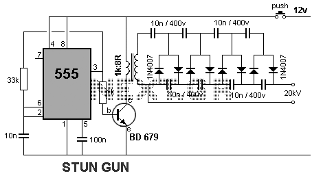
stun gun
This circuit generates a very high voltage, and precautions must be taken to avoid electric shock. The transformer can generate over 1,000 volts, while the 8-stage multiplier can produce up to 20,000 volts.
This high-voltage circuit typically consists of a step-up...

High Voltage Inverter
This is a simple high-voltage inverter circuit. It uses an NPN transistor type 2N3055. This circuit is designed to invert low voltage to high voltage.
The high-voltage inverter circuit utilizing the 2N3055 NPN transistor serves as an effective means to convert...

high voltage circuits
The diagram illustrates a series connection of cell diode capacitors, each rated for an increasing voltage of 300 V. This configuration generates a high DC voltage supply of 40 kV, which can be utilized for various experimental applications. With the...

High voltage power supply
Each subsequent stage adds 1700 volts, resulting in more than 20 kV with 12 stages. However, this voltage can only be achieved when the output of the cascade is unloaded.
The described circuit appears to be a high-voltage cascade generator, commonly...

Direct High Voltage DC Regulator
This regulator circuit stabilizes the output voltage at 200V directly (without a transformer). Although the output voltage is high, this circuit only suffers a.
The circuit in question is designed to maintain a stable output voltage of 200V without the use...

inverter circuit diagram
The double-ended working core square wave inverter transformer area product formula Bm represents the maximum magnetic flux. The primary side of the transformer features switches S1 and S2 in parallel with IRF32055. This parallel configuration is primarily due to the...

HELIUM NEON LASER SUPPLY
This figure illustrates a method for generating a momentary 10-kV voltage pulse to initiate plasma discharge across a laser tube. A diode voltage-multiplier circuit is connected in series with the main supply, obtaining its input power from one of the...