


Christmas Lights Sequencer Circuit using a 4017B
#4017B
#Christmas lights
#sequencer
#flashing lights
#holiday project
#decoration
#LED
#timer
#hobbyist
#seasonal

Description: Christmas is approaching, and it is the time of year when electronics students and hobbyists consider creating a Christmas circuit for their homes, particularly one that features flashing lights. Numerous circuits and kits are available that can flash various lights periodically, randomly, or sequentially. One versatile option that hobbyists or students can utilize to develop a simple Christmas Lights Sequencer for diverse seasonal lighting displays is the CMOS 4017B Johnson Counter. The 4017B is a fast-switching 5-stage Johnson decade counter equipped with ten fully decoded outputs, allowing for a total of ten individual light sources. These outputs activate sequentially, one at a time, with each positive-going edge of the clock pulse. At any given moment, only one output is at logic 1 (HIGH), while all others are at logic 0 (LOW), enabling a moving sequence or chaser effect, making the 4017 ideal for sequential LED or lighting displays in Christmas light projects. The 4017B operates as a circulating shift register, where its serial outputs connect back to its serial inputs to produce a specific sequence. Additionally, the 4017B Johnson counter can serve in frequency division applications, as well as in decade counter or decimal decode display applications. It is classified as a counter because it follows a defined sequence of states upon receiving a clock signal or pulse. As a synchronous counter, the switching action of all internal flip-flops is triggered by a common clock signal.
Before utilizing the 4017B Johnson counter in a Christmas lights sequencer circuit, a timing signal must be produced. Various methods exist for generating a timing or clock signal, including dedicated integrated circuits such as the NE555, discrete astable multivibrator circuits using transistors, or crystal oscillators. One straightforward and effective method for generating a square wave timing signal with minimal components is through the use of a Schmitt trigger inverter. The Schmitt trigger, named after its inventor, is a voltage level-sensitive two-state device functioning as an inverter or NOT gate. The advantage of employing a Schmitt trigger to generate a variable square wave timing signal lies in its specialized threshold circuit, which produces hysteresis, preventing erratic switching by "squaring up" the trigger voltage during transitions. This characteristic allows for reliable switching between HIGH and LOW (logic 0 and logic 1), making it ideal for generating square wave timing signals for the Christmas lights sequencer project.
In the configuration of the Schmitt inverter, when the potentiometer wiper is positioned at the bottom of the circuit, the voltage input to the Schmitt inverter remains low, indicating a logic level 0 and falling below the lower input threshold of the logic gate. As the Schmitt trigger operates as an inverter, this results in a high output at a logic level 1. When the potentiometer wiper is adjusted towards +5V, a point is reached where the voltage at the input (Vi) equals or exceeds the higher threshold input (VHTP), prompting the Schmitt inverter to switch states. At this stage, the input is at logic level 1, while the output shifts to logic level 0. Conversely, if the potentiometer wiper is at +5V and is gradually lowered towards 0V, there comes a point when the voltage at Vi equals or drops below the lower threshold input (VLTP), causing the Schmitt inverter to switch states again. By varying the voltage at the input of the Schmitt inverter between its upper and lower threshold trip points, the output can be made to change states, which is the fundamental principle behind generating a reliable clock signal for the Christmas lights sequencer.Christmas is coming and its that time of the year again when the electronics student or hobbyists thoughts turn to making a Christmas circuit for their home and especially one that flashes a few lights. There are many circuits and kits on the market that can flash any number of lights periodically, randomly or sequentially but one very versatile I
C that the hobbyist or student can use to produce a simple Christmas Lights Sequencer for use in a variety of different seasonal lighting displays is the CMOS 4017B Johnson Counter. The 4017B is a fast switching 5-stage Johnson decade counter complete with ten fully decoded outputs (making a total of 10 individual light sources).
These ten outputs switch sequentially one at a time on the arrival of each new positive-going edge of the clock pulse. Only one output is at logic 1 ³ or HIGH at any one moment while all others are cleared at logic 0 ³ or LOW , so it can produce a moving sequence or chaser effect, making the 4017 ideal as a sequential LED or lighting display for a Christmas lights project.
The 4017B is basically a circulating shift register in which its serial outputs are connected back to its serial inputs in order to produce a particular sequence. The 4017B Johnson counter can also be used in frequency division applications as well as decade counter or decimal decode display applications.
The 4017B is classified as counter because it exhibits a specified sequence of states upon the application of a clock signal or pulse. As the 4017B is used as a synchronous counter, the switching action of all the internal flip-flops are from the common clock signal as shown.
But before we can use the 4017B Johnson counter as part of our Christmas lights sequencer circuit, we need to produce a timing signal. There are many different ways of producing a timing or clock signal using dedicated IC`s such as the NE555 or discrete astable multivibrator circuits using transistors or crystal oscillators.
The list is endless. But one very simple and effective way of producing a square wave timing signal with the minimum of components is by using a Schmitt trigger inverter. The Schmitt Trigger, named after its inventor, is a voltage level sensitive two-state device in the form of an inverter or NOT-gate.
The advantage of using a Schmitt trigger to produce a variable square wave timing signal is that it uses a special threshold circuit that produces hysteresis, that prevents erratic switching by squaring up the trigger voltage as it switches between states. This allows reliable switching to occur between HIGH and LOW , or logic 0 ³ and logic 1 ³ making it ideal as a square wave timing signals for our Christmas lights sequencer project.
Consider the Schmitt Inverter as shown. When the position of the potentiometer wiper is at the bottom of the diagram, the voltage input to the Schmitt inverter is low representing a logic level 0 ³, and below the lower input threshold level of the logic gate. As the Schmitt trigger is an inverter, the resulting output will therefore be high at a logic level 1 ³.
As the potentiometers wiper is moved towards the +5V, there becomes a point when the voltage at Vi is equal or higher than the higher threshold input or higher trip point (VHTP) causing the Schmitt inverter to change state. There is now a situation were the input is at logic level 1 ³ and the output is at logic level 0 ³. Then the Schmitt trigger acts as an inverter or NOT Gate. Likewise, if the position of the potentiometer wiper is at +5V and lowered towards 0V, there becomes a point when the voltage at Vi is equal or lower than the lower threshold input or lower trip point (VLTP) causing the Schmitt inverter to change state once again.
Then by changing the value of the voltage on the input of the Schmitt inverter between its upper and lower threshold trip points, we can cause the output to change state, and this is the basic idea behind
Before utilizing the 4017B Johnson counter in a Christmas lights sequencer circuit, a timing signal must be produced. Various methods exist for generating a timing or clock signal, including dedicated integrated circuits such as the NE555, discrete astable multivibrator circuits using transistors, or crystal oscillators. One straightforward and effective method for generating a square wave timing signal with minimal components is through the use of a Schmitt trigger inverter. The Schmitt trigger, named after its inventor, is a voltage level-sensitive two-state device functioning as an inverter or NOT gate. The advantage of employing a Schmitt trigger to generate a variable square wave timing signal lies in its specialized threshold circuit, which produces hysteresis, preventing erratic switching by "squaring up" the trigger voltage during transitions. This characteristic allows for reliable switching between HIGH and LOW (logic 0 and logic 1), making it ideal for generating square wave timing signals for the Christmas lights sequencer project.
In the configuration of the Schmitt inverter, when the potentiometer wiper is positioned at the bottom of the circuit, the voltage input to the Schmitt inverter remains low, indicating a logic level 0 and falling below the lower input threshold of the logic gate. As the Schmitt trigger operates as an inverter, this results in a high output at a logic level 1. When the potentiometer wiper is adjusted towards +5V, a point is reached where the voltage at the input (Vi) equals or exceeds the higher threshold input (VHTP), prompting the Schmitt inverter to switch states. At this stage, the input is at logic level 1, while the output shifts to logic level 0. Conversely, if the potentiometer wiper is at +5V and is gradually lowered towards 0V, there comes a point when the voltage at Vi equals or drops below the lower threshold input (VLTP), causing the Schmitt inverter to switch states again. By varying the voltage at the input of the Schmitt inverter between its upper and lower threshold trip points, the output can be made to change states, which is the fundamental principle behind generating a reliable clock signal for the Christmas lights sequencer.Christmas is coming and its that time of the year again when the electronics student or hobbyists thoughts turn to making a Christmas circuit for their home and especially one that flashes a few lights. There are many circuits and kits on the market that can flash any number of lights periodically, randomly or sequentially but one very versatile I
C that the hobbyist or student can use to produce a simple Christmas Lights Sequencer for use in a variety of different seasonal lighting displays is the CMOS 4017B Johnson Counter. The 4017B is a fast switching 5-stage Johnson decade counter complete with ten fully decoded outputs (making a total of 10 individual light sources).
These ten outputs switch sequentially one at a time on the arrival of each new positive-going edge of the clock pulse. Only one output is at logic 1 ³ or HIGH at any one moment while all others are cleared at logic 0 ³ or LOW , so it can produce a moving sequence or chaser effect, making the 4017 ideal as a sequential LED or lighting display for a Christmas lights project.
The 4017B is basically a circulating shift register in which its serial outputs are connected back to its serial inputs in order to produce a particular sequence. The 4017B Johnson counter can also be used in frequency division applications as well as decade counter or decimal decode display applications.
The 4017B is classified as counter because it exhibits a specified sequence of states upon the application of a clock signal or pulse. As the 4017B is used as a synchronous counter, the switching action of all the internal flip-flops are from the common clock signal as shown.
But before we can use the 4017B Johnson counter as part of our Christmas lights sequencer circuit, we need to produce a timing signal. There are many different ways of producing a timing or clock signal using dedicated IC`s such as the NE555 or discrete astable multivibrator circuits using transistors or crystal oscillators.
The list is endless. But one very simple and effective way of producing a square wave timing signal with the minimum of components is by using a Schmitt trigger inverter. The Schmitt Trigger, named after its inventor, is a voltage level sensitive two-state device in the form of an inverter or NOT-gate.
The advantage of using a Schmitt trigger to produce a variable square wave timing signal is that it uses a special threshold circuit that produces hysteresis, that prevents erratic switching by squaring up the trigger voltage as it switches between states. This allows reliable switching to occur between HIGH and LOW , or logic 0 ³ and logic 1 ³ making it ideal as a square wave timing signals for our Christmas lights sequencer project.
Consider the Schmitt Inverter as shown. When the position of the potentiometer wiper is at the bottom of the diagram, the voltage input to the Schmitt inverter is low representing a logic level 0 ³, and below the lower input threshold level of the logic gate. As the Schmitt trigger is an inverter, the resulting output will therefore be high at a logic level 1 ³.
As the potentiometers wiper is moved towards the +5V, there becomes a point when the voltage at Vi is equal or higher than the higher threshold input or higher trip point (VHTP) causing the Schmitt inverter to change state. There is now a situation were the input is at logic level 1 ³ and the output is at logic level 0 ³. Then the Schmitt trigger acts as an inverter or NOT Gate. Likewise, if the position of the potentiometer wiper is at +5V and lowered towards 0V, there becomes a point when the voltage at Vi is equal or lower than the lower threshold input or lower trip point (VLTP) causing the Schmitt inverter to change state once again.
Then by changing the value of the voltage on the input of the Schmitt inverter between its upper and lower threshold trip points, we can cause the output to change state, and this is the basic idea behind

simple led torch circuit
This circuit is a simple LED torch utilizing the MAX660 integrated circuit from MAXIM semiconductors. The MAX660 is a CMOS monolithic voltage converter IC capable of driving three bright white LEDs connected in parallel to output pin 8 of the...

Timer Garage Door Circuit Schematic Diagram
Timer garage door circuit schematic diagram, printed circuit board.
The timer garage door circuit is designed to automate the opening and closing of a garage door based on a predetermined time interval. The schematic diagram illustrates the layout and connections of...

LED Christmas Star
This circuit can be used to construct an attractive Christmas Star. When we switch on this circuit, the brightness of lamp L1 gradually increases. When it reaches the maximum brightness level, the brightness starts decreasing gradually. And when it reaches...

Low Cost Dimmable Led Ballast Using The Valley Fill Current Shaping Circuit
The BFP640 transistor is utilized for 1575 MHz Global Positioning Satellite (GPS) applications, specifically as a Low Noise Amplifier (LNA). The design objectives include a minimum gain of 16 dB, a noise figure of less than 0.6 dB, an input/output...
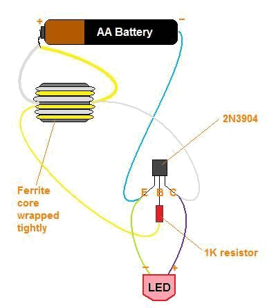
LED Grow Light using Joule Thief Battery Power
The title contains numerous words because this instructable integrates various concepts from multiple sources. The primary idea originated from Robomaniac's Desktop Energy Seed Lamp, combined with Witch's Growing Plants with LED Lights instructable and various wick gardening planters. The initial...

led interfacing with spartan 3e webserver
The Spartan-3E board features four LEDs connected to FPGA I/O pins, as detailed in the accompanying table. Each LED's cathode is connected to ground through a 330-ohm resistor. To illuminate a specific LED, the corresponding FPGA control signal must be...

led chasers
This summer, several LED projects were constructed, including sequential LED chasers that operate from left to right and a Nite-Rider style that moves sequentially left, right, left, right, and so on. These projects are enjoyable for children to experiment with....
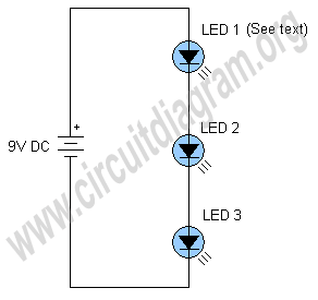
simplest led flasher
The schematic below illustrates a simple LED flasher circuit. This circuit utilizes three LEDs that begin to blink or flash upon receiving a 9-volt supply. It is straightforward in design, employing a self-flashing LED (LED 1) to trigger the flashing...
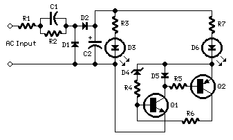
120 and 240Vac LED Indicator
This circuit, designed on request, has proven to be useful to indicate when the voltage in a power supply line is changing from 120V to 240Vac. It can be used in different circumstances and circuits, mainly when an increase in...