


Dc lamp dimmer
#dc lamp dimmer
#low power
#low cost
#potentiometer
#free-running multivibrator
#battery power
#portable
#flashlight
#heatsinking

Description: A low power, low cost DC lamp dimmer for a two-wire portable flashlight can be implemented with minimal or no heatsinking requirements. A single potentiometer, R3, is utilized to adjust the brightness of the lamp. Battery power is stored in capacitor C1 for the operational amplifier U1, which functions as a free-running multivibrator. The frequency of this multivibrator is determined by resistors R1, R2, R3, R4, and capacitor C2.
U1 drives the gate of transistor Q1, enabling it to switch the lamp ON and OFF at a frequency that is proportional to the duty cycle of the multivibrator.
This circuit operates on a simple principle of pulse-width modulation (PWM), allowing for efficient control of the lamp's brightness without significant power loss. The multivibrator generates a square wave signal, which modulates the power delivered to the lamp. The duty cycle of this signal, adjustable via the potentiometer R3, determines the average power reaching the lamp, thus controlling its brightness.
The components involved play specific roles: the capacitors (C1 and C2) store energy and help determine the timing characteristics of the multivibrator, while the resistors (R1, R2, R3, and R4) set the frequency and duty cycle of the PWM signal. The transistor Q1 acts as a switch, responding to the output from the multivibrator to control the lamp's operation.
This design is particularly advantageous for portable applications, such as flashlights, where battery life and heat management are critical. The low power consumption and minimal heat generation make this circuit suitable for long-duration use, ensuring that the flashlight can operate efficiently without overheating or requiring complex thermal management solutions.A low power, low cost dc lamp dimmer for a two-wire portable "flashlight" can be realized with little or no heatsinking. In addition, a single potentiometer, R3 adjusts lamp brightness. Battery power is stored in Cl for Ul, which is a free-running multivibrator whose frequency is determined by Rl, R2, R3, R4, and C2.
Ul drives the gate of Ql, turning it and the lamp ON and OFF at a rate proportional to the multivibrator duty cycle.
U1 drives the gate of transistor Q1, enabling it to switch the lamp ON and OFF at a frequency that is proportional to the duty cycle of the multivibrator.
This circuit operates on a simple principle of pulse-width modulation (PWM), allowing for efficient control of the lamp's brightness without significant power loss. The multivibrator generates a square wave signal, which modulates the power delivered to the lamp. The duty cycle of this signal, adjustable via the potentiometer R3, determines the average power reaching the lamp, thus controlling its brightness.
The components involved play specific roles: the capacitors (C1 and C2) store energy and help determine the timing characteristics of the multivibrator, while the resistors (R1, R2, R3, and R4) set the frequency and duty cycle of the PWM signal. The transistor Q1 acts as a switch, responding to the output from the multivibrator to control the lamp's operation.
This design is particularly advantageous for portable applications, such as flashlights, where battery life and heat management are critical. The low power consumption and minimal heat generation make this circuit suitable for long-duration use, ensuring that the flashlight can operate efficiently without overheating or requiring complex thermal management solutions.A low power, low cost dc lamp dimmer for a two-wire portable "flashlight" can be realized with little or no heatsinking. In addition, a single potentiometer, R3 adjusts lamp brightness. Battery power is stored in Cl for Ul, which is a free-running multivibrator whose frequency is determined by Rl, R2, R3, R4, and C2.
Ul drives the gate of Ql, turning it and the lamp ON and OFF at a rate proportional to the multivibrator duty cycle.

Low Power Regulator Reference
This is a simple circuit of a low-power voltage regulator reference. This circuit can produce a stable voltage reference.
The low-power voltage regulator reference circuit is designed to provide a consistent output voltage, which is crucial for various electronic applications requiring...

Flashlight circuit diagram of a motor control model
In the absence of light, photocells PC1 and PC2 exhibit high resistance, causing transistors Q1 and Q2 to remain off, which prevents the relay contacts K1 and K2 from closing. The battery B3 is connected through a potentiometer Rs, creating...

Low Power Negative Car Power Supply
I have had a lot of queries about getting a low power negative supply in cars, to power Linkwitz transform circuits and the like. There is a switchmode converter, but I must admit that it is overkill for what most...

Portable Nicad Charger
The portable charger is designed primarily for model enthusiasts to charge their NiCad batteries using a car battery outdoors. The circuit's supply voltage is regulated by IC1. When connected to the car battery, LED D2 illuminates only if the NiCad...

Flashing Flashlight
Pretty nice design for a cheap consumer grade flashlight. The power switch was not exactly as shown since there was an option to have the lamp on solid.
The described flashlight features a simple yet effective design aimed at consumer-grade applications....

Single Cell Battery 1.5V 20dB Inverting Amplifier
This amplifier circuit exhibits a very low power consumption, with a total current draw of 675 nA. The output voltage swing is 300 mV peak-to-peak (pp) with a gain of 20.
The amplifier circuit is designed to operate with minimal power...

The camera flashlight circuit
The camera flashlight circuit activates when switch K1 is engaged. This triggers a self-oscillating circuit consisting of BG1, capacitor C1, battery B1, and resistor R1. Once operational, the circuit boosts the voltage through B1 and rectifies it using diode D1...

Using tap potentiometer loudness circuit
Figure 1.88 illustrates the loudness control circuit utilizing multiple taps on a potentiometer. In Figure (A), the connection is made between the tap and the potentiometer's input, along with the ground. An RC compensation network is employed, where the slide...
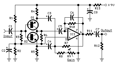
Portable Mixer
The target of this project was the design of a small portable mixer supplied by a 9V PP3 battery, keeping high quality performance. The mixer is formed assembling three main modules that can be varied in number and/or disposition to...