


DMX Lighting System
#DMX
#momentary switch
#current control
#potentiometer
#pulse width modulation
#10A switch
#lighting system
#safety
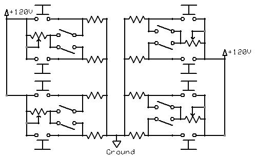
Description: The momentary switch utilized has a safety rating of 10A. If a switch is rated for a current that is too low, the instantaneous current during the first millisecond could cause the switch contacts to fuse together. To achieve the desired functionality, a switch capable of varying current is necessary. Possible options include a potentiometer, pulse width modulation, or a triac circuit (commonly used in light dimmers). In the schematic diagram, the light dimmer is represented by the potentiometer. However, a drawback of this circuit is the absence of an on/off switch. To resolve this issue, an on/off switch has been placed in series with the dimmer.
The circuit design incorporates a momentary switch rated for 10A, ensuring safety during operation. This switch is crucial for preventing potential failure due to excessive current, which could cause the contacts to weld together if the switch's current rating is inadequate. To allow for current variation, the circuit incorporates a potentiometer, which functions as a dimmer, providing a means to adjust the brightness of a connected load, such as a lamp.
In this configuration, the potentiometer is effectively used to modulate the power delivered to the load by varying the resistance in the circuit. However, this setup lacks a dedicated on/off mechanism, which is typically essential for user convenience. To address this limitation, an on/off switch has been integrated into the circuit design. This switch is placed in series with the potentiometer dimmer, allowing the user to completely disconnect the load from the power source when not in use.
The overall schematic showcases the relationship between these components, with clear indications of how the momentary switch, potentiometer, and on/off switch interact to control the flow of current. The inclusion of these elements not only enhances functionality but also prioritizes safety and user control, ensuring that the circuit operates effectively under varying conditions while minimizing the risk of component damage.The momentary switch used was rated for 10A for safty. If the switch was rated for too small a current, the instantaneous current for the first millisecond would fuse the switch contacts together. To achieve objective 3, some sort of switch that can vary current must be used. The posibilities are potentiometer, pulse width modulation, or a triac circuit (light dimmer). The light dimmer is represented by the potentiometer in the schematic diagram. The only problem with this circuit is that there is no on/off switch any more. To incorporate an on/off switch, I have chose to place it in series with the dimmer (shown below).
The circuit design incorporates a momentary switch rated for 10A, ensuring safety during operation. This switch is crucial for preventing potential failure due to excessive current, which could cause the contacts to weld together if the switch's current rating is inadequate. To allow for current variation, the circuit incorporates a potentiometer, which functions as a dimmer, providing a means to adjust the brightness of a connected load, such as a lamp.
In this configuration, the potentiometer is effectively used to modulate the power delivered to the load by varying the resistance in the circuit. However, this setup lacks a dedicated on/off mechanism, which is typically essential for user convenience. To address this limitation, an on/off switch has been integrated into the circuit design. This switch is placed in series with the potentiometer dimmer, allowing the user to completely disconnect the load from the power source when not in use.
The overall schematic showcases the relationship between these components, with clear indications of how the momentary switch, potentiometer, and on/off switch interact to control the flow of current. The inclusion of these elements not only enhances functionality but also prioritizes safety and user control, ensuring that the circuit operates effectively under varying conditions while minimizing the risk of component damage.The momentary switch used was rated for 10A for safty. If the switch was rated for too small a current, the instantaneous current for the first millisecond would fuse the switch contacts together. To achieve objective 3, some sort of switch that can vary current must be used. The posibilities are potentiometer, pulse width modulation, or a triac circuit (light dimmer). The light dimmer is represented by the potentiometer in the schematic diagram. The only problem with this circuit is that there is no on/off switch any more. To incorporate an on/off switch, I have chose to place it in series with the dimmer (shown below).

Ht48f06e Hopping Decoder
The Supertex HV440 is utilized for creating a pulse width modulated high voltage ring generator in telecommunication applications. The HV440 can function in both closed-loop and open-loop configurations. A closed-loop design, while more intricate, offers improved load regulation and lower...

Using tap potentiometer loudness circuit
Figure 1.88 illustrates the loudness control circuit utilizing multiple taps on a potentiometer. In Figure (A), the connection is made between the tap and the potentiometer's input, along with the ground. An RC compensation network is employed, where the slide...

Simple Safety Circuit Circuit
The simple two-hand safety control switch consists of two pushbutton switches connected in series; both must be depressed to energize the relay.
The two-hand safety control switch is designed to enhance safety in applications where the operation of machinery or equipment...

DMX Sequenced Servos
The project is inspired by the successful implementation of DMX sequencing with various Parallax products. The objective is to utilize the Propeller microcontroller to control not only lights but also motors, solenoids, servos, and other types of actuators. The analysis...
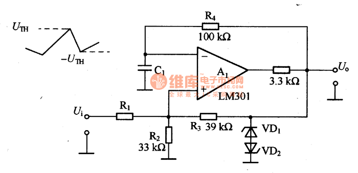
Simple pulse width modulation circuit
The simple pulse width modulation circuit is illustrated in the figure. It utilizes an operational amplifier to create a multivibrator, resulting in a symmetrical oscillation output signal with a duty cycle of 50%. By adjusting the external threshold voltage, pulse...

MC14093 pulse width modulation controller circuit design
A quad 2-input NAND Schmitt trigger circuit can be designed using the MC14093 CMOS type IC, which serves as a simple pulse width modulation (PWM) controller electronic project. This PWM controller is straightforward and requires only a few external electronic...

momentary switch teamed with
This circuit enables an SPST momentary pushbutton to function as a push-on, push-off switch by utilizing a DPDT latching (bi-stable) relay. It was designed to allow a single pushbutton switch on the dashboard of a vintage car to provide a...

music circuit
This circuit allows for the adjustment of resistance using a potentiometer and the adjustment of capacitance by opening or closing switches. By manipulating the configuration of these switches, various combinations can be achieved to obtain different effective capacitance values. It...

potentiometer Making an adjustable resistance
This part of the circuit is isolated from any other component, except for the 5V and ground connections. It includes LEDs and a shift register, which may not interact significantly. The LDR (Light Dependent Resistor) is utilized solely as a...