


dual led flasher by 2n2907
#led flasher
#2n2907
#transistor
#multivibrator
#flip flop
#pnp
#blinking circuit
#light control
#electronics hobbyist

Description: This circuit operates as a free-running multivibrator, resembling a flip-flop. It continuously oscillates on its own. The transistors Q1 and Q2 are PNP types, commonly used models include the 2N3906 and 2N2907. Resistors R1 and R2 limit the current flowing through the LED, which is bidirectional. Increasing the capacitance values of C1 and C2 will slow down the flashing rate of the LED. Enjoy experimenting with this LED flasher circuit.
The described circuit functions as a basic free-running multivibrator, which is an essential building block in digital electronics. The oscillation is achieved through the interplay of two PNP transistors, Q1 and Q2, configured in a feedback loop. When power is applied, one transistor turns on, allowing current to flow through its collector-emitter path, which in turn biases the other transistor into conduction. This feedback causes the transistors to switch states alternately, creating a square wave output.
The choice of transistors, such as the 2N3906 or 2N2907, ensures that the circuit can operate effectively with typical supply voltages and provides adequate current gain. The resistors R1 and R2 are critical for controlling the base current of the transistors, thereby regulating the brightness of the LED and preventing excessive current that could damage the components. The LED serves as a visual indicator of the oscillation, flashing on and off as the circuit operates.
Capacitors C1 and C2 are integral to determining the timing characteristics of the circuit. By adjusting their values, the time period of the oscillation can be modified, resulting in a faster or slower flash rate of the LED. Larger capacitance values will increase the time constant, thus slowing the flashing effect, while smaller values will produce a quicker flash.
This circuit can be utilized in various applications, including visual indicators, timers, and simple light effects. It serves as an excellent project for beginners looking to understand the principles of oscillation and transistor operation in electronic circuits. Proper attention should be given to component ratings and power supply to ensure reliable performance.This circuit calls more Free Running Multivibrator work resemble Flip Flop. Which encourage itself repeatedly. The Q1 and Q2 be Transistor PNP be usable general (2N3906, 2N2907, etc. ) The R1 and R2 limit current that flow through LED the bilateral. If enhance the value C1 and C2 the rate something Flasher slow down. Request friends have fun LED Fla sher, this please sir.
The described circuit functions as a basic free-running multivibrator, which is an essential building block in digital electronics. The oscillation is achieved through the interplay of two PNP transistors, Q1 and Q2, configured in a feedback loop. When power is applied, one transistor turns on, allowing current to flow through its collector-emitter path, which in turn biases the other transistor into conduction. This feedback causes the transistors to switch states alternately, creating a square wave output.
The choice of transistors, such as the 2N3906 or 2N2907, ensures that the circuit can operate effectively with typical supply voltages and provides adequate current gain. The resistors R1 and R2 are critical for controlling the base current of the transistors, thereby regulating the brightness of the LED and preventing excessive current that could damage the components. The LED serves as a visual indicator of the oscillation, flashing on and off as the circuit operates.
Capacitors C1 and C2 are integral to determining the timing characteristics of the circuit. By adjusting their values, the time period of the oscillation can be modified, resulting in a faster or slower flash rate of the LED. Larger capacitance values will increase the time constant, thus slowing the flashing effect, while smaller values will produce a quicker flash.
This circuit can be utilized in various applications, including visual indicators, timers, and simple light effects. It serves as an excellent project for beginners looking to understand the principles of oscillation and transistor operation in electronic circuits. Proper attention should be given to component ratings and power supply to ensure reliable performance.This circuit calls more Free Running Multivibrator work resemble Flip Flop. Which encourage itself repeatedly. The Q1 and Q2 be Transistor PNP be usable general (2N3906, 2N2907, etc. ) The R1 and R2 limit current that flow through LED the bilateral. If enhance the value C1 and C2 the rate something Flasher slow down. Request friends have fun LED Fla sher, this please sir.

Symmetric Noise Source
When a transistor junction operates in Zener breakdown as a noise source, the resulting noise signal exhibits asymmetry in amplitude. This issue can be addressed by employing two transistors as independent noise sources. One transistor is connected with a series...
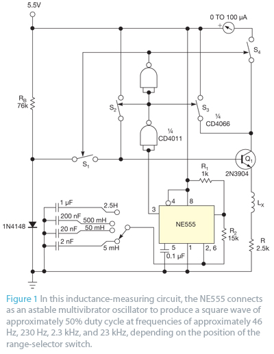
Use a transistor and an ammeter to measure inductance
Bipolar junction transistors transfer a current from a lower-resistance emitter to a higher-resistance collector. This property can be utilized to measure inductance.
Bipolar junction transistors (BJTs) are semiconductor devices that play a crucial role in electronic circuits by enabling the control...
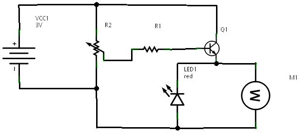
Transistor Current Amplifier Circuit
In a prior post titled "Timing is Everything," the application of PWM (Pulse Width Modulation) signals for controlling devices such as LEDs was discussed. This technique is particularly beneficial when working with digital devices, including microchips and microcontrollers, which often...

Motor vehicle steering flasher 12
The motor vehicle steering flasher described in the example utilizes high-power transistors as electronic switches, and the circuit is simple and easy to construct. The motor vehicle steering flasher consists of the flash circuit with resistors R1-R3, a capacitor C,...

T3SE type 3 SE
The all-transistor T3SE operates similarly to a conventional switch mode power supply (SE). Like the Tritium model, it activates when the charging current falls below a specified threshold. After the circuit is triggered, positive feedback is utilized to latch the...

Recording signal amplifying transistor circuit
This circuit is a recording signal amplifying transistor circuit that illustrates the functioning of a microphone signal amplifier. After adjustment through potentiometer RP1, the signal is applied to the transistor VT1, which operates as a common emitter amplifier. The emitter...

easy build motocycle alarm
The circuit requires two transistors to drive a relay, which acts as a switch to activate a buzzer. Any number of normally-open switches may be applied. Mercury switches should be installed to ensure they close when the steering is engaged....

Simple preamplifier circuits by transistors
When there is a need to amplify audio signals from various sources before they reach a custom amplifier, a preamplifier (or preamp) is typically employed. This document suggests a specific circuit that is interesting due to its use of a...

simple intercom circuit with
This is a two-station simple intercom circuit built using transistors and common 8-ohm mini speakers. The speaker functions as a microphone and generates sound, eliminating the need for a separate microphone in this intercom setup. The "press-to-talk" switches should have...