


Emergency lighting circuit diagram

Description: The device circuit operates as illustrated in Figure 11. Power outages are a common occurrence, but in certain situations, maintaining power is critical, such as during ongoing surgeries. The circuit employs a simple design that is fully automated. When 220V AC is present, lamp H1 illuminates, and the output from the LSE is high, causing transistor VT to remain off, which prevents relay J from activating and lamp H2 from lighting. In the event of a power outage, H1 turns off, the output from the LSE drops low, and transistor VT conducts, activating relay J and illuminating lamp H2. This setup allows for an automatic transition between the two lamps during power interruptions.
The circuit described functions as an automatic power backup system, utilizing a relay and transistors to manage the transition between power sources. The primary power source is 220V AC, which powers lamp H1 under normal operating conditions. The LSE (likely a low-voltage sensor or controller) monitors the voltage levels and provides an output signal that controls the transistor VT.
When the AC power is present, lamp H1 serves as an indicator light, signaling normal operation. The high output from the LSE keeps the transistor VT in a non-conductive state, which means that relay J remains deactivated. Consequently, lamp H2, which acts as the backup light, remains off.
During a power outage, the sudden loss of AC voltage causes lamp H1 to extinguish. The LSE detects this drop in voltage and its output signal transitions to a low state. This change turns on transistor VT, which then conducts and activates relay J. The relay, upon being energized, connects the power supply to lamp H2, causing it to illuminate automatically. This seamless transition between lamps ensures that there is minimal disruption in lighting, which is particularly important in critical situations such as surgeries.
The design of this circuit emphasizes reliability and simplicity, making it suitable for applications where continuous lighting is essential. The use of a relay provides a robust method for switching between power sources, while the transistor acts as an efficient control element, allowing for quick responses to changes in power availability. Overall, this automated system enhances safety and operational continuity during power interruptions.The device circuit works shown in Figure 11. Power outages are frequent thing, but some occasions, the power does not allow (such as the ongoing surgery, etc.). LSE with simple circuit design, fully automated. When 220V AC, the lamp H1 lights up, while the LSE feet high output, transistor VT end, the relay J is released, it does not shine direct light H2. Once a power outage, H1 off, LSE's pin output low, then transistor VT conduction, the relay J pull, turn the power lights H2, H2 light automatically convert between almost two lights interruption.
The circuit described functions as an automatic power backup system, utilizing a relay and transistors to manage the transition between power sources. The primary power source is 220V AC, which powers lamp H1 under normal operating conditions. The LSE (likely a low-voltage sensor or controller) monitors the voltage levels and provides an output signal that controls the transistor VT.
When the AC power is present, lamp H1 serves as an indicator light, signaling normal operation. The high output from the LSE keeps the transistor VT in a non-conductive state, which means that relay J remains deactivated. Consequently, lamp H2, which acts as the backup light, remains off.
During a power outage, the sudden loss of AC voltage causes lamp H1 to extinguish. The LSE detects this drop in voltage and its output signal transitions to a low state. This change turns on transistor VT, which then conducts and activates relay J. The relay, upon being energized, connects the power supply to lamp H2, causing it to illuminate automatically. This seamless transition between lamps ensures that there is minimal disruption in lighting, which is particularly important in critical situations such as surgeries.
The design of this circuit emphasizes reliability and simplicity, making it suitable for applications where continuous lighting is essential. The use of a relay provides a robust method for switching between power sources, while the transistor acts as an efficient control element, allowing for quick responses to changes in power availability. Overall, this automated system enhances safety and operational continuity during power interruptions.The device circuit works shown in Figure 11. Power outages are frequent thing, but some occasions, the power does not allow (such as the ongoing surgery, etc.). LSE with simple circuit design, fully automated. When 220V AC, the lamp H1 lights up, while the LSE feet high output, transistor VT end, the relay J is released, it does not shine direct light H2. Once a power outage, H1 off, LSE's pin output low, then transistor VT conduction, the relay J pull, turn the power lights H2, H2 light automatically convert between almost two lights interruption.

led traffic lights
The LED traffic light circuit manages six LEDs (red, yellow, and green) for both north/south and east/west traffic directions. The timing sequence is produced using a CMOS 4017 decade counter in conjunction with a 555 timer. Outputs 1 through 4...

LED-Circuits 4
This is a constant current source using a FET. It serves as a simple replacement for a series resistor to limit current. The N-Channel FET BF256C can provide a current of 15mA. Before using integrated circuits, it is advisable to...

Dancing LED's circuit
Here is a simple circuit which can be used for decoration purposes or as an indicator. Flashing or dancing speed of LEDs can be adjusted and various dancing patterns of lights can be formed. The circuit consists of two astable...

Lighting designs with flicker-free LED dimming
LED lighting is becoming increasingly prominent in both residential and commercial lighting markets. To enhance the success and adoption of solid-state lighting in retrofit lamps, it is essential for LED lamps to support dimming with existing controllers and wiring. However,...
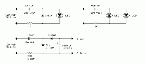
AC Line powered LEDs
The circuit below demonstrates how to power one or two LEDs from a 120-volt AC line. It utilizes a capacitor to reduce the voltage and a small resistor to limit the inrush current. As the capacitor needs to allow current...

Automotive LED Timing Light
A timing strobe can be constructed using high-brightness LEDs and a few common components. Ignition pulses from the number one cylinder high-tension lead are used to trigger the circuit via a homemade inductive pickup. Transistors Q1 and Q2 buffer and...

LED STEREO SOUND LEVEL INDICATOR
LED stereo sound level indicator for audio amplifier. Many circuits can be designed as level indicators by using a comparator IC or transistors, but...
The LED stereo sound level indicator serves as a visual representation of the audio signal levels in...

Flicker frequency of multiple sets of different light-emitting diode lights chain circuit
The circuit utilizes a 555 timer configured as a multivibrator, where the oscillation frequency is determined by resistors R1, R2, and capacitor C1. The frequency formula is given by fo = 1.443 / ((R1 + R2) * C1). The output...

LED light chaser using 4017
This is a LED sequencer circuit where 10 LEDs light up and turn off sequentially, creating a chasing effect. This simple circuit is suitable for designing lighting decorations on Christmas trees. It can also be used for lighting animations by...