


Family Kara OK lights 5GM168 a control circuit diagram
#karaoke
#lighting control
#four-way output
#loop jump
#speed control
#LED
#entertainment
#family use
#circuit design

Description: This document describes a family karaoke lighting design that employs various methods to control the circuit. The control circuit presented here features a four-way light output with loop jumping and speed control capabilities. The practical circuit utilizes a microphone to detect sound, allowing the lights to jump in response to the strength of the acoustic signal; stronger signals result in faster light jumps, while weaker signals produce slower responses. The home lighting control circuit comprises a power supply circuit, a control circuit, and an audio amplifier.
The family karaoke lighting design integrates an innovative control mechanism that enhances the user experience by synchronizing light patterns with audio input. The circuit architecture includes three primary components: a power supply circuit, a control circuit, and an audio amplifier, each playing a crucial role in the overall functionality.
The power supply circuit is responsible for providing the necessary voltage and current to the entire system, ensuring stable operation. It typically consists of a transformer, rectifier, and filter capacitors to convert AC voltage from the mains supply to the required DC voltage for the control circuit and audio amplifier.
The control circuit is the core of the lighting system, utilizing a microcontroller or a combination of logic gates to process the audio signals captured by the microphone. The circuit is designed to interpret the amplitude of the incoming sound waves, allowing it to modulate the speed and pattern of the light outputs. The four-way light output can be achieved using an array of LEDs or light bulbs, each connected to a relay or transistor switch that is controlled by the microcontroller. The loop jumping feature allows for dynamic transitions between different light patterns, enhancing the visual effects in synchronization with the music.
The audio amplifier serves to boost the signal received from the microphone, ensuring that even quieter sounds can be detected and processed by the control circuit. This component typically includes operational amplifiers configured in a non-inverting mode to provide gain, along with filtering stages to eliminate noise and enhance the clarity of the audio signal.
In summary, this karaoke lighting control circuit is a sophisticated system that combines audio detection with responsive lighting effects. It provides an engaging environment for home entertainment by allowing users to experience a vibrant light show that reacts in real-time to the music being played.Family karaoke 0K lighting design of a variety of methods to control circuit, the control circuit described here is a kind of four-way light output, loop jump, speed controllab le practical circuit. Microphone to pick up speed to jump the lights with acoustic signal strength varies, acoustic signal stronger, faster jump lights, whereas the slower speed. home lighting control circuit is shown. The circuit consists of a power supply circuit, a control circuit and audio amplifier.
The family karaoke lighting design integrates an innovative control mechanism that enhances the user experience by synchronizing light patterns with audio input. The circuit architecture includes three primary components: a power supply circuit, a control circuit, and an audio amplifier, each playing a crucial role in the overall functionality.
The power supply circuit is responsible for providing the necessary voltage and current to the entire system, ensuring stable operation. It typically consists of a transformer, rectifier, and filter capacitors to convert AC voltage from the mains supply to the required DC voltage for the control circuit and audio amplifier.
The control circuit is the core of the lighting system, utilizing a microcontroller or a combination of logic gates to process the audio signals captured by the microphone. The circuit is designed to interpret the amplitude of the incoming sound waves, allowing it to modulate the speed and pattern of the light outputs. The four-way light output can be achieved using an array of LEDs or light bulbs, each connected to a relay or transistor switch that is controlled by the microcontroller. The loop jumping feature allows for dynamic transitions between different light patterns, enhancing the visual effects in synchronization with the music.
The audio amplifier serves to boost the signal received from the microphone, ensuring that even quieter sounds can be detected and processed by the control circuit. This component typically includes operational amplifiers configured in a non-inverting mode to provide gain, along with filtering stages to eliminate noise and enhance the clarity of the audio signal.
In summary, this karaoke lighting control circuit is a sophisticated system that combines audio detection with responsive lighting effects. It provides an engaging environment for home entertainment by allowing users to experience a vibrant light show that reacts in real-time to the music being played.Family karaoke 0K lighting design of a variety of methods to control circuit, the control circuit described here is a kind of four-way light output, loop jump, speed controllab le practical circuit. Microphone to pick up speed to jump the lights with acoustic signal strength varies, acoustic signal stronger, faster jump lights, whereas the slower speed. home lighting control circuit is shown. The circuit consists of a power supply circuit, a control circuit and audio amplifier.

Using LEDs as colour sensors
This circuit converts the analog signal from the reversed LED, which is in sensing mode, and amplified by the operational amplifier, into a digital (on/off) signal. The original complex design has been simplified. An alternative approach is discussed in a...

Color Sensor from a Reversed LED and Op Amp
One of the first lessons that electronics students learn is that an LED emits light when current flows through it. However, it is also true that when an LED is connected in reverse, it can generate a current flow when...

Implementing Adaptive Brightness Control to Seven Segment LED Displays
An automatic brightness adjustment is a closed-loop system that has the capability to assess ambient light and adjust the brightness of the display accordingly.
The automatic brightness adjustment circuit operates by utilizing a light sensor, typically a photoresistor (LDR) or photodiode,...

LED torch using MAX660
This is a simple LED torch circuit based on the MAX660 integrated circuit from MAXIM semiconductors. The MAX660 is a CMOS monolithic voltage converter IC capable of driving three bright white LEDs connected in parallel to output pin 8. The...
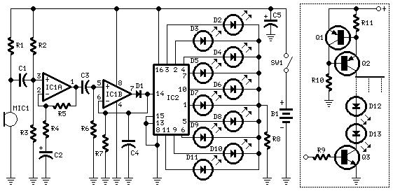
10 Dancing LEDs
The basic circuit illuminates up to ten LEDs in sequence, following the rhythm of music or speech picked up by a small microphone. The expanded version can drive up to ten strips, formed by up to five LEDs each, at...
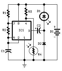
LED Night Lamp
This circuit is usable as a Night Lamp when a wall mains socket is not available to plug-in an ever running small neon lamp device. In order to ensure minimum battery consumption, one 1.5V cell is used, and a simple...

LED Dimmer Lighting
A dimmer for individual LED bulbs. LEDs (light emitting diodes) are very sensitive components; exceeding their rated current or voltage can drastically reduce their lifespan from over 50,000 hours to mere microseconds. LEDs are current-driven, meaning that the intensity of...

LED Boost Circuit
The completed board may be driven by voltages between 0.8 and 3 Volts. While the basic design goal was candle-like light from a single cell, the values used were chosen to allow safe operation from 3 Volts so you can,...
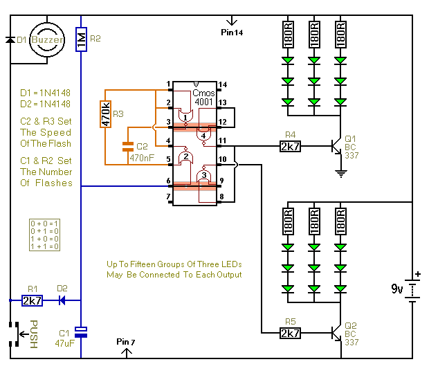
Three Flashing LED Doorbells For The Hearing Impaired
When the push switch is activated, the buzzer sounds, and the LEDs start to flash. For the hearing members of the household, the buzzer functions as a standard doorbell, providing reassurance to the visitor that the doorbell is operational. Upon...