


Five stalls can control fan speed optical circuit
#fan speed control
#capacitor step-down
#voltage regulator
#7806
#ceiling fan
#speed control circuit
#fixed regulator
#home automation
#electrical control

Description: The ceiling fan speed control circuit depicted in Figure 3-6 utilizes a capacitor step-down method and a three-terminal fixed 7806 voltage regulator. It achieves fan speed control through the integrated circuit A2, which regulates the conduction angle of the Triac V. The circuit is activated by pressing the button SB, allowing A2 to cycle through different speed settings, effectively reducing the conduction angle to control the fan speed.
The ceiling fan speed control circuit is designed to modulate the speed of a ceiling fan using a combination of a capacitor step-down method and a voltage regulation approach. The circuit incorporates a three-terminal fixed voltage regulator, specifically the 7806, which provides a steady output voltage of 6V. This stable voltage is essential for the reliable operation of the integrated circuit A2, which manages the fan speed.
The control mechanism involves a Triac, designated as V, which regulates the power delivered to the fan motor by altering its conduction angle. The conduction angle is the portion of the AC cycle during which the Triac is turned on, thereby controlling the amount of power supplied to the fan. By adjusting this angle, the fan speed can be varied smoothly.
User interaction with the circuit is facilitated through a push-button switch, labeled SB. When pressed, this switch initiates a sequence in which the integrated circuit A2 cycles through predefined speed settings. This cycling allows for multiple speed options, typically ranging from low to high, and includes an off setting. Each speed corresponds to a specific conduction angle, with lower speeds achieved by reducing the conduction angle, thus providing a finer control over the fan's operation.
This circuit design exemplifies a practical application of power electronics in home appliances, demonstrating how simple components can work together to achieve efficient and user-friendly control of ceiling fan speeds. Proper implementation of this circuit ensures that the fan operates quietly and efficiently at the desired speed, enhancing comfort in living spaces.Fans (Ceiling) Fifth gear speed control circuit shown in Figure 3-6. It uses capacitor step-down, three-terminal fixed 7806 integrated steady voltage regulator Ai regulator to achieve fan speed control integrated circuit A2 through LC906 control Triac V conduction angle. Order press the button SB. A2 will be 4 feet by a block 1 block 2 block -3 -4 -5 stop a block off a one block. cycling issue a control signal, so that V conduction block smaller race, to achieve speed.
The ceiling fan speed control circuit is designed to modulate the speed of a ceiling fan using a combination of a capacitor step-down method and a voltage regulation approach. The circuit incorporates a three-terminal fixed voltage regulator, specifically the 7806, which provides a steady output voltage of 6V. This stable voltage is essential for the reliable operation of the integrated circuit A2, which manages the fan speed.
The control mechanism involves a Triac, designated as V, which regulates the power delivered to the fan motor by altering its conduction angle. The conduction angle is the portion of the AC cycle during which the Triac is turned on, thereby controlling the amount of power supplied to the fan. By adjusting this angle, the fan speed can be varied smoothly.
User interaction with the circuit is facilitated through a push-button switch, labeled SB. When pressed, this switch initiates a sequence in which the integrated circuit A2 cycles through predefined speed settings. This cycling allows for multiple speed options, typically ranging from low to high, and includes an off setting. Each speed corresponds to a specific conduction angle, with lower speeds achieved by reducing the conduction angle, thus providing a finer control over the fan's operation.
This circuit design exemplifies a practical application of power electronics in home appliances, demonstrating how simple components can work together to achieve efficient and user-friendly control of ceiling fan speeds. Proper implementation of this circuit ensures that the fan operates quietly and efficiently at the desired speed, enhancing comfort in living spaces.Fans (Ceiling) Fifth gear speed control circuit shown in Figure 3-6. It uses capacitor step-down, three-terminal fixed 7806 integrated steady voltage regulator Ai regulator to achieve fan speed control integrated circuit A2 through LC906 control Triac V conduction angle. Order press the button SB. A2 will be 4 feet by a block 1 block 2 block -3 -4 -5 stop a block off a one block. cycling issue a control signal, so that V conduction block smaller race, to achieve speed.

12 Volt 30 Amp Power Supply
This power supply utilizes a single 7812 integrated circuit (IC) voltage regulator in conjunction with multiple external pass transistors to provide output load currents of up to 30 amps.
The circuit design incorporates a 7812 voltage regulator, which is known for...
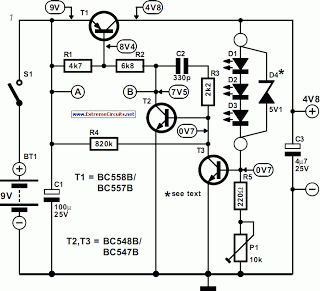
thrifty voltage regulator
One of the drawbacks of a three-pin voltage regulator is that the input voltage needs to be 2.5 to 3 V higher than the output voltage. This makes these integrated regulators unsuitable for battery power supplies. For instance, if the...
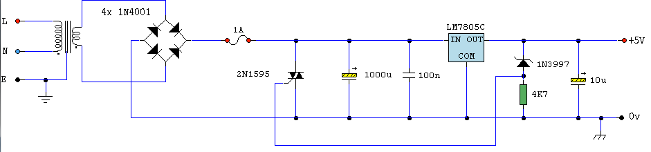
Logic PSU With Over-Voltage Protection
A simple 5 Volt regulated power supply unit (PSU) featuring overvoltage protection. This 5 Volt regulated power supply is designed for TTL and 74LS series integrated circuits.
The 5 Volt regulated power supply unit is an essential component in electronic designs...
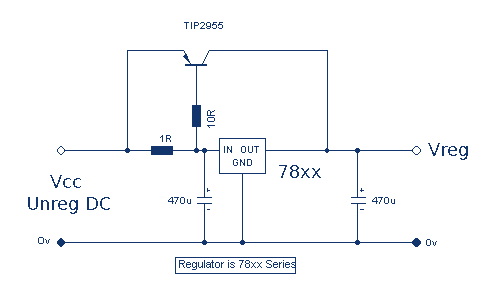
Increasing Regulator Current
Although the 78xx series of voltage regulators are available with different current outputs, you can boost the available current output with this circuit. A power transistor is used to supply extra current to the load, maintaining a constant voltage. Currents...

0-50V 1A power supply with CA3086
This power supply circuit is highly stabilized that its output voltage will drop only 0.005% even though the load changes from 0 to 100%. Another excellent capability is that the output voltage will change only by 0.01% if the input...

Universal Laboratory Power Supply Circuit
The design's value is derived from the use of IC1, an LM317HVK adjustable series-pass voltage regulator, which provides broad-range performance along with voltage-setting and current-limiting functions. The input to IC1 is sourced from the output of BR1, which is filtered...

DC Power Supply 9 volt using TIP31 transistor
This is a DC power supply circuit designed to regulate 9 volts and provide a current output ranging from 1 amp to 2 amps. The circuit utilizes a modified TIP31 transistor, although alternative transistors such as TIP41, MJE3055, or 2SC1061...

voltage regulator circuit with pass
This is a simple design for a voltage regulator circuit using a pass transistor. The design is built around the LM317T. The output current of the LM317T can be increased by incorporating an additional power transistor to share a portion...

35 Ampere Power Supply
A 12 Volt 35 Amp power supply can be constructed using the LM7812 voltage regulator to provide a stable 12 Volt DC output. The power supply employs TIP2955 transistors as the main power regulators, with a configuration that utilizes six...