


Halogen Lamp Protector Circuit
#halogen lamp
#soft turn-on
#MOSFET
#BUZ10
#filament protection
#power management
#lighting control
#circuit protection

Description: This circuit produces a soft turn-on for halogen lamp filaments upon powering up. The MOSFET used is a BUZ10, which has a resistance of 0.2 ohms. Resistors R1, R2, and capacitor C1 set the turn-on rate, while diode D1 discharges capacitor C1 at turn-off.
The circuit employs a BUZ10 MOSFET to control the power delivered to halogen lamp filaments, allowing for a gradual increase in brightness rather than an abrupt illumination. This soft start feature is particularly beneficial for extending the lifespan of the halogen lamps, as it reduces thermal stress on the filaments during power-up.
Resistor R1 and resistor R2 form a voltage divider that influences the gate voltage of the MOSFET, effectively controlling the turn-on time. The time constant for the turn-on process is determined by the values of R1, R2, and the capacitance of C1. A larger capacitance or higher resistance values will result in a slower increase in voltage at the gate, leading to a softer turn-on.
Capacitor C1 plays a crucial role in the timing of the turn-on process. When power is applied, C1 charges through the resistors, gradually increasing the gate voltage until it reaches the threshold voltage of the MOSFET, causing it to turn on. The diode D1 is connected in parallel with C1 and ensures that when the power is turned off, C1 discharges quickly, allowing the MOSFET to turn off rapidly and preventing any residual voltage that could keep the lamp glowing.
The design of this circuit is essential for applications where a sudden surge of current could damage sensitive components or reduce the lifespan of the halogen lamps. By utilizing the BUZ10 MOSFET, which has a low on-resistance of 0.2 ohms, the circuit minimizes power loss and heat generation during operation, enhancing efficiency and reliability. Overall, this soft turn-on circuit is a practical solution for controlling halogen lamps in various lighting applications. This circuit, produces a soft turn-on for halogen lamp filaments upon powering up. MOSFET used is a BUZ10, which has 0.2 Rm on. Rl, R2, and CI set the turn-on rate and D1 discharges CI at turn-off.
The circuit employs a BUZ10 MOSFET to control the power delivered to halogen lamp filaments, allowing for a gradual increase in brightness rather than an abrupt illumination. This soft start feature is particularly beneficial for extending the lifespan of the halogen lamps, as it reduces thermal stress on the filaments during power-up.
Resistor R1 and resistor R2 form a voltage divider that influences the gate voltage of the MOSFET, effectively controlling the turn-on time. The time constant for the turn-on process is determined by the values of R1, R2, and the capacitance of C1. A larger capacitance or higher resistance values will result in a slower increase in voltage at the gate, leading to a softer turn-on.
Capacitor C1 plays a crucial role in the timing of the turn-on process. When power is applied, C1 charges through the resistors, gradually increasing the gate voltage until it reaches the threshold voltage of the MOSFET, causing it to turn on. The diode D1 is connected in parallel with C1 and ensures that when the power is turned off, C1 discharges quickly, allowing the MOSFET to turn off rapidly and preventing any residual voltage that could keep the lamp glowing.
The design of this circuit is essential for applications where a sudden surge of current could damage sensitive components or reduce the lifespan of the halogen lamps. By utilizing the BUZ10 MOSFET, which has a low on-resistance of 0.2 ohms, the circuit minimizes power loss and heat generation during operation, enhancing efficiency and reliability. Overall, this soft turn-on circuit is a practical solution for controlling halogen lamps in various lighting applications. This circuit, produces a soft turn-on for halogen lamp filaments upon powering up. MOSFET used is a BUZ10, which has 0.2 Rm on. Rl, R2, and CI set the turn-on rate and D1 discharges CI at turn-off.

Transistor Tutorial MOSFETs
The Metal-Oxide-Semiconductor Field-Effect Transistor (MOSFET) is analogous to the Junction Field-Effect Transistor (JFET) in several aspects. Both types are voltage-driven unipolar devices that rely on either electron or hole movement, but not both, unlike bipolar transistors. A key structural distinction...
70W High Power Amplifier with MOSFET
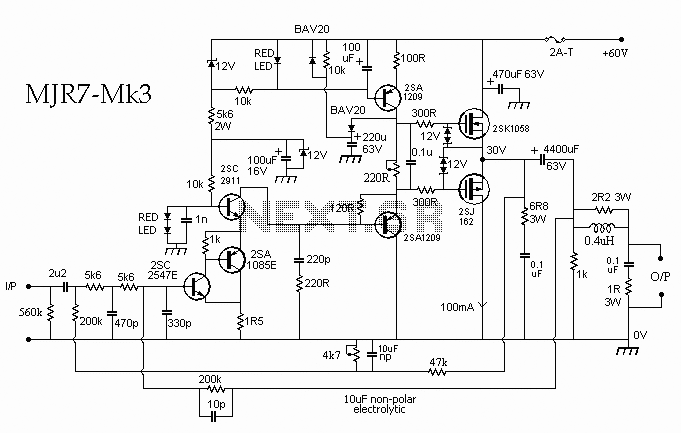
This schematic diagram illustrates a 70W power amplifier utilizing MOSFET technology for audio systems. Alternative input stage transistors include the Toshiba 2SA970BL and 2SC2240BL, which serve as suitable substitutes for the Hitachi 2SA1085E.
The 70W power amplifier is designed to deliver...

Linear Light Dimmer by Power Mosfet
Changing the value of R2 alters the intensity of the lamp in this circuit, demonstrating the utility of a MOSFET as a variable resistor. An N-Channel Power MOSFET, designated as Q1, is utilized in the circuit. The specific part number...

High power mosfet amplifier circuit ideas
The power amplifier circuit utilizing MOSFET technology has gained significant popularity due to its aggressive sound characteristics when compared to traditional transistors and integrated circuits. It offers both low-frequency and high-frequency responses and is known for its durability. Generally, when...

Linear MOSFET voltage regulator
The circuit is a MOSFET based linear voltage regulator with a voltage drop of as low as 60 mV at 1 ampere. Drop of a fewer millivolts is possible with better MOSFETs having lower RDS(on) resistance. The circuit uses a...

100 Watt MOSFET Power Amplifier
One still designing that it uses in the exit transistor of technology V-mosfet. This transistors to us offer a lot of virtues concerning the simple bipolar transistors, as high speeds, thermic stability, low distortion etc. Beyond this circuit use also...

On After Delay with Mosfet
This is an On After Delay Circuit. It utilizes a MOSFET in the circuit for easier delay implementation compared to using a transistor. The operation of the circuit begins when switch S1 is pressed.
The On After Delay Circuit is designed...

MOSFET based step-up joule thief circuit
It employs a low threshold MOSFET and two coupled coils to function as a joule thief. An additional MOSFET is utilized for regulation.
The circuit operates as a joule thief, which is a type of DC-DC converter designed to extract energy...

make this 1kva 1000 watts pure sine
The configuration depicted in the first diagram is a straightforward MOSFET-based design intended for current amplification at +/-60 volts, enabling the connected transformer to produce the required 1 kVA output. Transistors Q1 and Q2 constitute the initial differential amplifier stage,...