


How does LED Flashes One by One in my Project Some Queries

Description: A project called LED Flasher that sequentially flashes LEDs one by one. There is a query regarding the project, and any simple explanation would be greatly appreciated. A reference image or a link can be used for additional context.
The LED Flasher project is designed to create a visual effect by illuminating a series of light-emitting diodes (LEDs) in a sequential manner. This type of circuit is often utilized in decorative lighting, signaling devices, and educational demonstrations of electronic principles.
The core of this project typically involves a microcontroller or a simple timer circuit that controls the timing and order of the LED activation. A common choice for such a project is the use of a 555 timer IC configured in astable mode, which generates a continuous square wave output. This output can be fed into a series of transistors, each connected to an individual LED.
The circuit may include the following key components:
1. **Microcontroller or Timer IC**: This component serves as the brain of the circuit. If using a microcontroller like an Arduino, it can be programmed to control the timing and sequence of LED activation through digital output pins. Alternatively, a 555 timer can be used for simpler applications.
2. **Resistors**: These are used to limit the current flowing through the LEDs to prevent them from burning out. The value of the resistors can be calculated using Ohm's law based on the forward voltage and current rating of the LEDs.
3. **Transistors**: If the circuit uses a microcontroller, transistors may be employed as switches to drive the LEDs. This is particularly useful when the total current required by the LEDs exceeds the output current capacity of the microcontroller pins.
4. **Power Supply**: A suitable power supply is essential to provide the necessary voltage and current for the circuit operation. This could be a battery or a DC power source, depending on the application.
5. **LEDs**: The choice of LEDs can vary based on the desired visual effect. Different colors can be used, and the arrangement can affect the overall aesthetic of the flashing sequence.
The operation of the LED Flasher can be summarized as follows: the microcontroller or timer generates a signal that turns on one LED at a time in a predetermined sequence. The timing of each LED activation can be adjusted to create different flashing patterns, such as a simple chase effect or more complex animations.
In conclusion, the LED Flasher project serves as an excellent introduction to basic electronic components and circuit design, allowing users to explore concepts such as timing, sequencing, and current control in a practical and visually appealing way.A project called LED Flasher which Flashes LED`s one by one . but I have following Query about my project . if anyone can explain me it in simple words it will be great help for me . one can use Below image for reference or use this link
The LED Flasher project is designed to create a visual effect by illuminating a series of light-emitting diodes (LEDs) in a sequential manner. This type of circuit is often utilized in decorative lighting, signaling devices, and educational demonstrations of electronic principles.
The core of this project typically involves a microcontroller or a simple timer circuit that controls the timing and order of the LED activation. A common choice for such a project is the use of a 555 timer IC configured in astable mode, which generates a continuous square wave output. This output can be fed into a series of transistors, each connected to an individual LED.
The circuit may include the following key components:
1. **Microcontroller or Timer IC**: This component serves as the brain of the circuit. If using a microcontroller like an Arduino, it can be programmed to control the timing and sequence of LED activation through digital output pins. Alternatively, a 555 timer can be used for simpler applications.
2. **Resistors**: These are used to limit the current flowing through the LEDs to prevent them from burning out. The value of the resistors can be calculated using Ohm's law based on the forward voltage and current rating of the LEDs.
3. **Transistors**: If the circuit uses a microcontroller, transistors may be employed as switches to drive the LEDs. This is particularly useful when the total current required by the LEDs exceeds the output current capacity of the microcontroller pins.
4. **Power Supply**: A suitable power supply is essential to provide the necessary voltage and current for the circuit operation. This could be a battery or a DC power source, depending on the application.
5. **LEDs**: The choice of LEDs can vary based on the desired visual effect. Different colors can be used, and the arrangement can affect the overall aesthetic of the flashing sequence.
The operation of the LED Flasher can be summarized as follows: the microcontroller or timer generates a signal that turns on one LED at a time in a predetermined sequence. The timing of each LED activation can be adjusted to create different flashing patterns, such as a simple chase effect or more complex animations.
In conclusion, the LED Flasher project serves as an excellent introduction to basic electronic components and circuit design, allowing users to explore concepts such as timing, sequencing, and current control in a practical and visually appealing way.A project called LED Flasher which Flashes LED`s one by one . but I have following Query about my project . if anyone can explain me it in simple words it will be great help for me . one can use Below image for reference or use this link
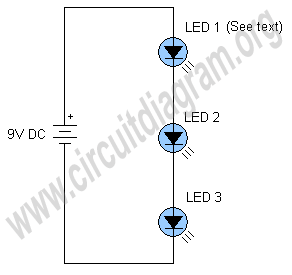
simplest led flasher
The schematic below illustrates a simple LED flasher circuit. This circuit utilizes three LEDs that begin to blink or flash upon receiving a 9-volt supply. It is straightforward in design, employing a self-flashing LED (LED 1) to trigger the flashing...

turret diy
For maximum mini-security, this RC Tupperware Turret delivers a formidable deterrent against food theft. While it lacks motion sensors, potential food thieves will think twice before attempting to swipe baked goods. This 11-hour project, designed by Chris of PyroElectro, emphasizes...

LED Flashlight Use Super capacitor Schematic Diagram
Tired of experimenting with capacitors? It's time to explore supercapacitors, which offer significant storage capabilities. This article provides instructions on building a small LED flashlight utilizing supercapacitors. A minimum voltage of 2 volts is necessary to illuminate the LED, as...

Key Illuminator Circuit
Used as a 10-second momentary illuminator, this circuit can be useful in other applications as well. Pressing SI charges CI, which holds Q1 on and keeps the LED lit for about 10 seconds.
The circuit described functions as a momentary illuminator,...
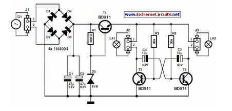
LED Bike Light Circuit Project
A front wheel with a built-in dynamo was purchased, providing a sine wave output of 30 Vpp at no load. Based on this, a simple power supply was designed using BD911 transistors, which are somewhat oversized for the application, but...
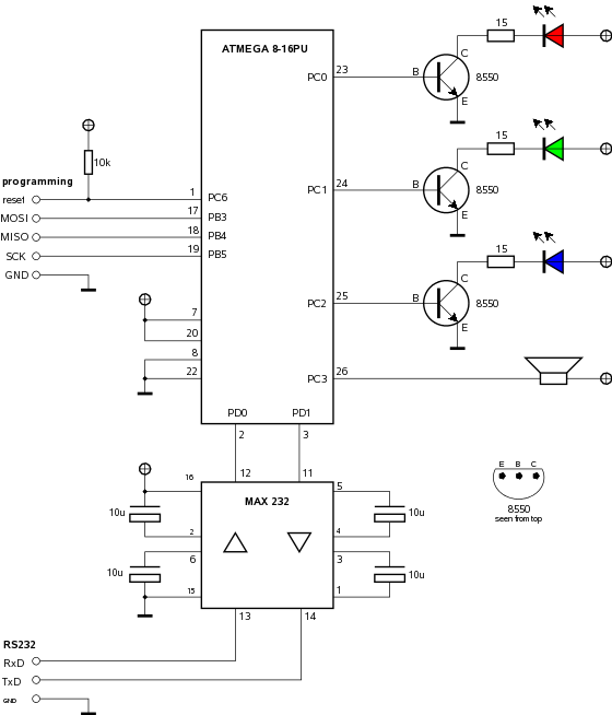
ledlamp
Building a computer-controlled LED lamp with an ATMEL microcontroller.
The project involves designing a computer-controlled LED lamp utilizing an ATMEL microcontroller as the central processing unit. The core components of this circuit include the ATMEL microcontroller, a power supply, various LEDs,...

one transistor led flasher
This is a one-transistor LED flasher circuit designed to flash a super bright LED. The circuit employs a single transistor as a driver, which receives the flash rate from LED 2, a self-flashing LED. The flash rate can be adjusted...
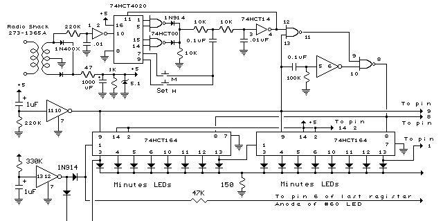
28 LED Clock schematic
In the circuit below, 60 individual LEDs are used to indicate the minutes of a clock and 12 LEDs indicate hours. The power supply and time base circuitry is the same as described in the 28 LED clock circuit above....

Phone in use indicator by LED
This circuit is useful to show when your line is busy. I used for this a pair of SMT transistors, the LEDs on when the voltage drops down to 40 V.
The circuit described functions as an indicator for a busy...