


Lantern with dimmer and flasher

Description: The electronic lantern control circuit adds high-efficiency dimming and flashing to an existing battery-powered lantern or flashlight or to a custom design. For the car it makes a great lamp for changing a flat tire, back seat reading or emergency engine work. The flasher mode is useful for warning other drivers of your troubles and it may be adjusted to have a very short flash duration for long-term use as when the car must be left on the shoulder overnight. When camping it is great as a low-power night light for the tent or the portable 'potty'--you may select only as much light as you need! More: The flasher mode is useful for finding a boat dock in the dark or even attracting fish. At home, the flasher is a great way to tell guests when they have found the right house or to "jazz up" battery powered holiday decorations. The circuit is intended for 6 or 12 volt lantern batteries but it should work well with supplies from 4.5 to 15 volts without any modifications to the circuit as shown above. Except C1/C3. If you intend to use 12 to 15V, increase the working voltage of these two capacitors to 25V instead of the listed 16V. In dimmer mode (switch S1 open), the circuit sends rapid variable-width pulses to the bulb to control the brightness and in flasher mode (switch S1 closed) the pulse rate is about one per second. Very short flashes will give a greatly extended battery life. The TIP32 remains cool since it switches on and off instead of simply dropping the voltage like a power rheostat. The components are not critical and substitutions are fine. Almost any general-purpose op-amps or comparators will work in place of the LM358. The two transistors may be replaced by a power FET if desired simply by connecting the gate to pin 7 of the Op-Amp, the source to ground, and the drain to the bulb. The other end of the bulb connects to the positive terminal of the battery in this case. There is nothing particularly critical about the resistor and capacitor values and the experimenter may change them, if desired. For example, a 10K-pot may be substituted for the 5K by increasing the 3.9K resistors by 2 also (8.2K would be fine). The 100K's in the flash circuit may be a different value if the capacitors are also scaled (inversely--if the resistors are doubled, the 0.1 and 10uF are halved). For Q1 (2N4401), a PN100 or a BJT like the 2N3904 should work fine also. Power transistor Q2 (TIP32) can be replaced with a NTE197 or a NTE292. Try experimenting with whatever you have at hand or combine values to get the desired value you want. Construction is not critical - the entire circuit may be built on a piece of perf-board and wrapped with electrical tape. An old gas-mantle lantern could be converted over to battery power by placing a bulb socket in place of the mantle and building a battery compartment in the fuel tank. Q1 is a NPN audio amp transistor and can be substituted with a 2N3904, PN100, NTE123AP, the BC547, Elector's TUN, etc. Q2 is a PNP power amp and can be substituted with a NTE197. Try others, they also may work.
The electronic lantern control circuit is designed to enhance the functionality of battery-powered lanterns or flashlights by integrating a dimming and flashing feature. This circuit is particularly beneficial in various scenarios, such as automotive emergencies, camping, and home use. The circuit can operate effectively with battery voltages ranging from 4.5 to 15 volts, allowing for versatility in application.
In the circuit, a key component is the operational amplifier (op-amp), specifically the LM358, which can be replaced with other general-purpose op-amps or comparators without affecting performance. The circuit operates in two modes: dimmer mode and flasher mode, which is controlled by a switch (S1). In dimmer mode, the circuit sends rapid variable-width pulses to the bulb, allowing for brightness adjustment. Conversely, in flasher mode, the circuit generates approximately one pulse per second, providing a flashing effect ideal for signaling or attracting attention.
The TIP32 power transistor is utilized in the circuit to manage the power delivered to the bulb. It operates efficiently by switching on and off, which prevents excessive heat generation compared to traditional rheostatic voltage drop methods. If a higher voltage supply (12-15V) is used, it is recommended to increase the voltage rating of capacitors C1 and C3 to 25V to ensure reliability.
The circuit design allows for component substitution, offering flexibility for users to utilize available parts. For instance, the NPN transistor Q1 (2N4401) can be replaced with other NPN types like the 2N3904 or PN100, while the power transistor Q2 can be substituted with alternatives such as NTE197 or NTE292. Resistor and capacitor values are not critical, allowing for experimentation to achieve desired performance characteristics.
Construction of the circuit can be accomplished on a perf-board, with the option to enclose it in electrical tape for insulation and protection. The design allows for creative adaptations, such as converting traditional gas lanterns to battery-powered models by integrating a bulb socket and a battery compartment, thus expanding the utility of existing equipment.
Overall, the electronic lantern control circuit presents a practical solution for enhancing lighting devices, offering adjustable brightness and signaling capabilities in a compact and efficient design.The electronic lantern control circuit adds high-efficiency dimming and flashing to an existing battery-powered lantern or flashlight or to a custom design. For the car it makes a great lamp for changing a flat tire, back seat reading or emergency engine work.
The flasher mode is useful for warning other drivers of your troubles and it may be adjusted to have a very short flash duration for long-term use as when the car must be left on the shoulder over night.When camping it is great as a low-power night light for the tent or the portable 'potty'--you may select only as much light as you need! The flasher mode is useful for finding a boat dock in the dark or even attracting fish. At home, the flasher is a great way to tell guests when they have found the right house or to "jazz up" battery powered holiday decorations. The circuit is intended for 6 or 12 volt lantern batteries but it should work well with supplies from 4.5 to 15 volts without any modifications to the circuit as shown above.
Except C1/C3. If you intend to use 12 to 15V, increase the working voltage of these two capacitors to 25V instead of the listed 16V. In dimmer mode (switch S1 open), the circuit send rapid variable-width pulses to the bulb to control the brightness and in flasher mode (switch S1 closed) the pulse rate is about one per second.
Very short flashes will give a greatly extended battery life. The TIP32 remains cool since it switches on and off instead of simply dropping the voltage like a power rheostat. The components are not critical and substitutions are fine. Almost any general purpose op-amps or comparators will work in place of the LM358. The two transistors may be replaced by a power FET if desired simply by connecting the gate to pin 7 of the Op-Amp, the source to ground, and the drain to the bulb.
The other end of the bulb connects to the positive terminal of the battery in this case. There is nothing particularly critical about the resistor and capacitor values and the experimenter may change them, if desired. For example, a 10K-pot may be substituted for the 5K by increasing the 3.9K resistors by 2 also (8.2K would be fine).
The 100K's in the flash circuit may be a different value if the capacitors are also scaled (inversely--if the resistors are doubled, the 0.1 and 10uF are halved). For Q1 (2N4401), a PN100 or a BJT like the 2N3904 should work fine also. Power transistor Q2 (TIP32) can be replaced with a NTE197 or a NTE292. Try experimenting with whatever you have at hand or combine values to get the desired value you want.
Construction is not critical - the entire circuit may be built on a piece of perf-board and wrapped with electrical tape. An old gas-mantle lantern could be converted over to battery power by placing a bulb socket in place of the mantle and building a battery compartment in the fuel tank.
Q1 is a NPN audio amp transistor and can be substituted with a 2N3904, PN100, NTE123AP, the BC547, Elector's TUN, etc. Q2 is a PNP power amp and can be substituted with a NTE197. Try others, they also may work.
The electronic lantern control circuit is designed to enhance the functionality of battery-powered lanterns or flashlights by integrating a dimming and flashing feature. This circuit is particularly beneficial in various scenarios, such as automotive emergencies, camping, and home use. The circuit can operate effectively with battery voltages ranging from 4.5 to 15 volts, allowing for versatility in application.
In the circuit, a key component is the operational amplifier (op-amp), specifically the LM358, which can be replaced with other general-purpose op-amps or comparators without affecting performance. The circuit operates in two modes: dimmer mode and flasher mode, which is controlled by a switch (S1). In dimmer mode, the circuit sends rapid variable-width pulses to the bulb, allowing for brightness adjustment. Conversely, in flasher mode, the circuit generates approximately one pulse per second, providing a flashing effect ideal for signaling or attracting attention.
The TIP32 power transistor is utilized in the circuit to manage the power delivered to the bulb. It operates efficiently by switching on and off, which prevents excessive heat generation compared to traditional rheostatic voltage drop methods. If a higher voltage supply (12-15V) is used, it is recommended to increase the voltage rating of capacitors C1 and C3 to 25V to ensure reliability.
The circuit design allows for component substitution, offering flexibility for users to utilize available parts. For instance, the NPN transistor Q1 (2N4401) can be replaced with other NPN types like the 2N3904 or PN100, while the power transistor Q2 can be substituted with alternatives such as NTE197 or NTE292. Resistor and capacitor values are not critical, allowing for experimentation to achieve desired performance characteristics.
Construction of the circuit can be accomplished on a perf-board, with the option to enclose it in electrical tape for insulation and protection. The design allows for creative adaptations, such as converting traditional gas lanterns to battery-powered models by integrating a bulb socket and a battery compartment, thus expanding the utility of existing equipment.
Overall, the electronic lantern control circuit presents a practical solution for enhancing lighting devices, offering adjustable brightness and signaling capabilities in a compact and efficient design.The electronic lantern control circuit adds high-efficiency dimming and flashing to an existing battery-powered lantern or flashlight or to a custom design. For the car it makes a great lamp for changing a flat tire, back seat reading or emergency engine work.
The flasher mode is useful for warning other drivers of your troubles and it may be adjusted to have a very short flash duration for long-term use as when the car must be left on the shoulder over night.When camping it is great as a low-power night light for the tent or the portable 'potty'--you may select only as much light as you need! The flasher mode is useful for finding a boat dock in the dark or even attracting fish. At home, the flasher is a great way to tell guests when they have found the right house or to "jazz up" battery powered holiday decorations. The circuit is intended for 6 or 12 volt lantern batteries but it should work well with supplies from 4.5 to 15 volts without any modifications to the circuit as shown above.
Except C1/C3. If you intend to use 12 to 15V, increase the working voltage of these two capacitors to 25V instead of the listed 16V. In dimmer mode (switch S1 open), the circuit send rapid variable-width pulses to the bulb to control the brightness and in flasher mode (switch S1 closed) the pulse rate is about one per second.
Very short flashes will give a greatly extended battery life. The TIP32 remains cool since it switches on and off instead of simply dropping the voltage like a power rheostat. The components are not critical and substitutions are fine. Almost any general purpose op-amps or comparators will work in place of the LM358. The two transistors may be replaced by a power FET if desired simply by connecting the gate to pin 7 of the Op-Amp, the source to ground, and the drain to the bulb.
The other end of the bulb connects to the positive terminal of the battery in this case. There is nothing particularly critical about the resistor and capacitor values and the experimenter may change them, if desired. For example, a 10K-pot may be substituted for the 5K by increasing the 3.9K resistors by 2 also (8.2K would be fine).
The 100K's in the flash circuit may be a different value if the capacitors are also scaled (inversely--if the resistors are doubled, the 0.1 and 10uF are halved). For Q1 (2N4401), a PN100 or a BJT like the 2N3904 should work fine also. Power transistor Q2 (TIP32) can be replaced with a NTE197 or a NTE292. Try experimenting with whatever you have at hand or combine values to get the desired value you want.
Construction is not critical - the entire circuit may be built on a piece of perf-board and wrapped with electrical tape. An old gas-mantle lantern could be converted over to battery power by placing a bulb socket in place of the mantle and building a battery compartment in the fuel tank.
Q1 is a NPN audio amp transistor and can be substituted with a 2N3904, PN100, NTE123AP, the BC547, Elector's TUN, etc. Q2 is a PNP power amp and can be substituted with a NTE197. Try others, they also may work.

LED Colour Organ circuit
Most existing designs utilize direct switching of lights without any software control and include manual potentiometers for light sensitivity and overall gain settings. There are limited references regarding the frequency filter circuitry, explaining the specific frequencies the circuit is designed...

ALPHANUMERIC LED DISPLAY PROJECT
A tiny sandwich flag connected perpendicular to the motor spindle aids observation of how long it takes to complete one full rotation. This worked initially, as each burst from the capacitor barely moved the flag 1/4 of a rotation. As...

Mains operated led Lamp
This circuit operates 25 LEDs powered by a mains supply of 230V. A fluorescent lamp adapter was acquired from a scrap dealer for ease of disassembly.
The circuit consists of a series of 25 light-emitting diodes (LEDs) arranged to operate from...
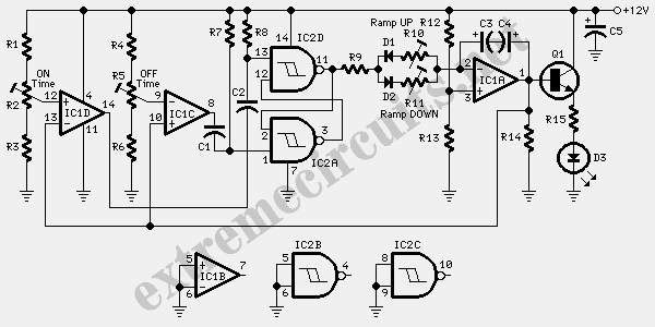
Fine Control Super Bright LED Pulser
The circuit utilizes two white LEDs, with the second LED connected across the emitter of the transistor and the negative ground. It requires its own limiting resistor in series, similar to R15 and D3 in the circuit diagram. If standard...

Ice warning and lights reminder
This device informs a driver whether their lights should be activated and warns them if the outside temperature approaches zero degrees Celsius by illuminating an LED and sounding a buzzer. The sensitivity can be adjusted using VR1, and the light-dependent...

Touching dimmer circuit composed of S7232
A touch dimmer circuit is illustrated in the accompanying diagram. It utilizes a finger touch control piece to enable the turning on, off, or stepless adjustment of incandescent lighting. This circuit is applicable in dimming filament lamps and for the...
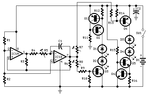
Fading LEDs
This circuit operates two LED strips in pulsing mode, i.e. one LED strip goes from off state, lights up gradually, then dims gradually, etc. while the other LED strip does the contrary. Each strip can be made up from 2...

LED torch using NSI45090JDT4G constant current regulator
A very simple LED torch can be designed using the NSI45090JDT4G adjustable constant current regulator (CCR) from ON Semiconductor, utilizing very few external components. The NSI45090JDT4G device provides a cost-effective solution for regulating current in LEDs. This constant current regulator...

lamp dimmer
This is an advanced dimmer circuit design that allows the triac to be triggered at lower voltage levels. Typically, the triggering voltage for a triac is approximately 70V; however, this circuit enables triggering at around 35V through the incorporation of...