


led chaser provides three game
#LED chaser
#game circuit
#heads or tails
#dice simulator
#roulette sound
#speaker
#light effects
#gaming
#interactive
#educational

Description: This circuit functions as a light chaser and can be configured to simulate either a heads or tails game (Two Up) or a dice game. It incorporates a speaker to replicate the sound of a spinning roulette wheel. The features for dice and heads/tails can be omitted if desired, allowing for customizable game rules, such as implementing betting or recording numbers to determine the highest score per game. The circuit utilizes IC1, a 4046 phase-locked loop (PLL), specifically employing the voltage-controlled oscillator (VCO) section to generate clock pulses for IC2, a 4017 decade counter/divider. In roulette wheel mode, activating switch S3 initiates the game, charging a 10 µF capacitor at pin 9. As this capacitor discharges, the output frequency gradually decreases, slowing the rate of the chaser LEDs driven by IC2. In chaser mode, closing switch S2 provides a fixed frequency output from IC1, which can be adjusted over a broad range using potentiometer VR1. Transistor Q1 is activated by the oscillator output of IC1, driving the speaker, while trimpot VR2 adjusts the sound level, and switch S4 can turn it off. Switch S5 allows selection between the dice game or other modes (chaser/roulette). In dice mode, pin 6 is connected to the reset pin 15, limiting the count to 6, whereas in other modes, the count extends to 10, illuminating all LEDs. Pin 12 controls transistor Q2 and two LEDs to facilitate the heads/tails function.
This circuit design integrates several essential components to create an engaging and interactive gaming experience. The 4046 PLL not only serves as a clock generator but also allows for precise control over the frequency of the output signal, which is critical for the visual effects produced by the chaser LEDs. The 4017 decade counter effectively counts the pulses from the VCO, enabling the sequential illumination of the LEDs in a chaser pattern, which can be visually appealing and captivating for users.
The circuit's versatility is highlighted by its ability to switch between different game modes. The use of switches S2, S3, and S5 allows users to easily transition between the roulette and dice functionalities. The design also accommodates user preferences by enabling the removal of certain features, thus tailoring the gameplay experience. The adjustable potentiometer VR1 provides further customization, allowing users to set the speed of the chaser LEDs according to their liking.
Sound integration is achieved through the use of the speaker driven by transistor Q1. The sound effects enhance the gaming experience, simulating the ambiance of a casino environment. The inclusion of trimpot VR2 for sound level adjustment ensures that the audio output can be tailored to suit different settings, whether for quiet play or a more immersive experience.
Overall, this circuit represents a well-thought-out design that combines visual and auditory elements to create a fun and engaging device suitable for various gaming scenarios. The thoughtful arrangement of components and the ability to customize features make it a versatile platform for entertainment.This circuit is essentially a light chaser but it can also be set to provides heads or tails (Two Up) or a Dice (die). It also has a speaker to simulate the sound of a spinning roulette wheel. Note that the dice and heads/tails features can be deleted if required and rules for the games created to suit individuals; eg, betting can be used or the n
umbers recorded and then totalled to get the highest score per game. IC1 is a 4046 phase locked loop (PLL) but only the voltage controlled oscillator (VCO) portion of the chip is used to provide the clock pulse for IC2, a 4017 decade counter/divider. In roulette wheel mode, switch S3 is pushed to start the game. This charges the 10 F capacitor at pin 9 and as the capacitor discharges, the output frequency is slowly reduced to slow the rate of the chaser LEDs driven by IC2.
In chaser mode, switch S2 is closed to provide a fixed frequency output from IC1. This can be varied over a wide range with potentiometer VR1. Transistor Q1 is also driven by the oscillator output of IC1 and it drives the speaker. Trimpot VR2 varies the sound level while switch S4 turns it off. Switch S5 selects Die or other (chaser/roulette). In Die mode, pin 6 is connected to the reset, pin 15, so that the circuit only counts to 6 whereas in the other modes it counts to 10 and displays all LEDs. Pin 12 drives transistor Q2 and two LEDs to provide the Heads/Tails function.
This circuit design integrates several essential components to create an engaging and interactive gaming experience. The 4046 PLL not only serves as a clock generator but also allows for precise control over the frequency of the output signal, which is critical for the visual effects produced by the chaser LEDs. The 4017 decade counter effectively counts the pulses from the VCO, enabling the sequential illumination of the LEDs in a chaser pattern, which can be visually appealing and captivating for users.
The circuit's versatility is highlighted by its ability to switch between different game modes. The use of switches S2, S3, and S5 allows users to easily transition between the roulette and dice functionalities. The design also accommodates user preferences by enabling the removal of certain features, thus tailoring the gameplay experience. The adjustable potentiometer VR1 provides further customization, allowing users to set the speed of the chaser LEDs according to their liking.
Sound integration is achieved through the use of the speaker driven by transistor Q1. The sound effects enhance the gaming experience, simulating the ambiance of a casino environment. The inclusion of trimpot VR2 for sound level adjustment ensures that the audio output can be tailored to suit different settings, whether for quiet play or a more immersive experience.
Overall, this circuit represents a well-thought-out design that combines visual and auditory elements to create a fun and engaging device suitable for various gaming scenarios. The thoughtful arrangement of components and the ability to customize features make it a versatile platform for entertainment.This circuit is essentially a light chaser but it can also be set to provides heads or tails (Two Up) or a Dice (die). It also has a speaker to simulate the sound of a spinning roulette wheel. Note that the dice and heads/tails features can be deleted if required and rules for the games created to suit individuals; eg, betting can be used or the n
umbers recorded and then totalled to get the highest score per game. IC1 is a 4046 phase locked loop (PLL) but only the voltage controlled oscillator (VCO) portion of the chip is used to provide the clock pulse for IC2, a 4017 decade counter/divider. In roulette wheel mode, switch S3 is pushed to start the game. This charges the 10 F capacitor at pin 9 and as the capacitor discharges, the output frequency is slowly reduced to slow the rate of the chaser LEDs driven by IC2.
In chaser mode, switch S2 is closed to provide a fixed frequency output from IC1. This can be varied over a wide range with potentiometer VR1. Transistor Q1 is also driven by the oscillator output of IC1 and it drives the speaker. Trimpot VR2 varies the sound level while switch S4 turns it off. Switch S5 selects Die or other (chaser/roulette). In Die mode, pin 6 is connected to the reset, pin 15, so that the circuit only counts to 6 whereas in the other modes it counts to 10 and displays all LEDs. Pin 12 drives transistor Q2 and two LEDs to provide the Heads/Tails function.

6V Ultra-Bright LED Chaser
This is a spectacular but completely useless project. It lights Ultra-Bright LEDs in a sequence and each LED flashes brightly very briefly. The LEDs light-up going around and around since they are mounted in a circle (on a CD), then...

White Light
White Light is an interactive sound and light installation that combines elements of sculpture, musical instrument, and social engagement. It invites viewers to participate in a complex display of sound and light by manipulating controls on one of three podiums...

A simple three-way speaker crossover circuit diagram
The divider acts as the speaker's brain and is crucial for sound quality. The music amplifier's output signal must be processed through a wave filter element to divide it into specific frequency signals for each unit. A scientifically and rationally...

Electronics Cricket
The electronics cricket game circuit presented on this website is a straightforward and easy-to-build circuit diagram for an electronics cricket project, as well as various other game projects.
The electronics cricket game circuit typically consists of several key components that work...

doorphone intercom
An 8-ohm speaker functions as both a microphone and an output device. The BC109C transistor operates in common base mode, providing substantial voltage gain while ensuring a low impedance input suitable for the speaker. Self DC biasing is implemented to...

16 LED Chaser
This circuit is a double direction flash. Similar to Digital Ping-Pong 1, there is a movement of a lit dot, up and down along the LED's length. When the D16 lit the situation changes and there is a reverse movement....

Speaker Mic Circuit
This circuit enables the use of an inexpensive loudspeaker as a microphone. Sound waves that reach the speaker cone create fluctuations in the voice coil. The movement of the voice coil within the speaker's magnetic field generates a small electrical...
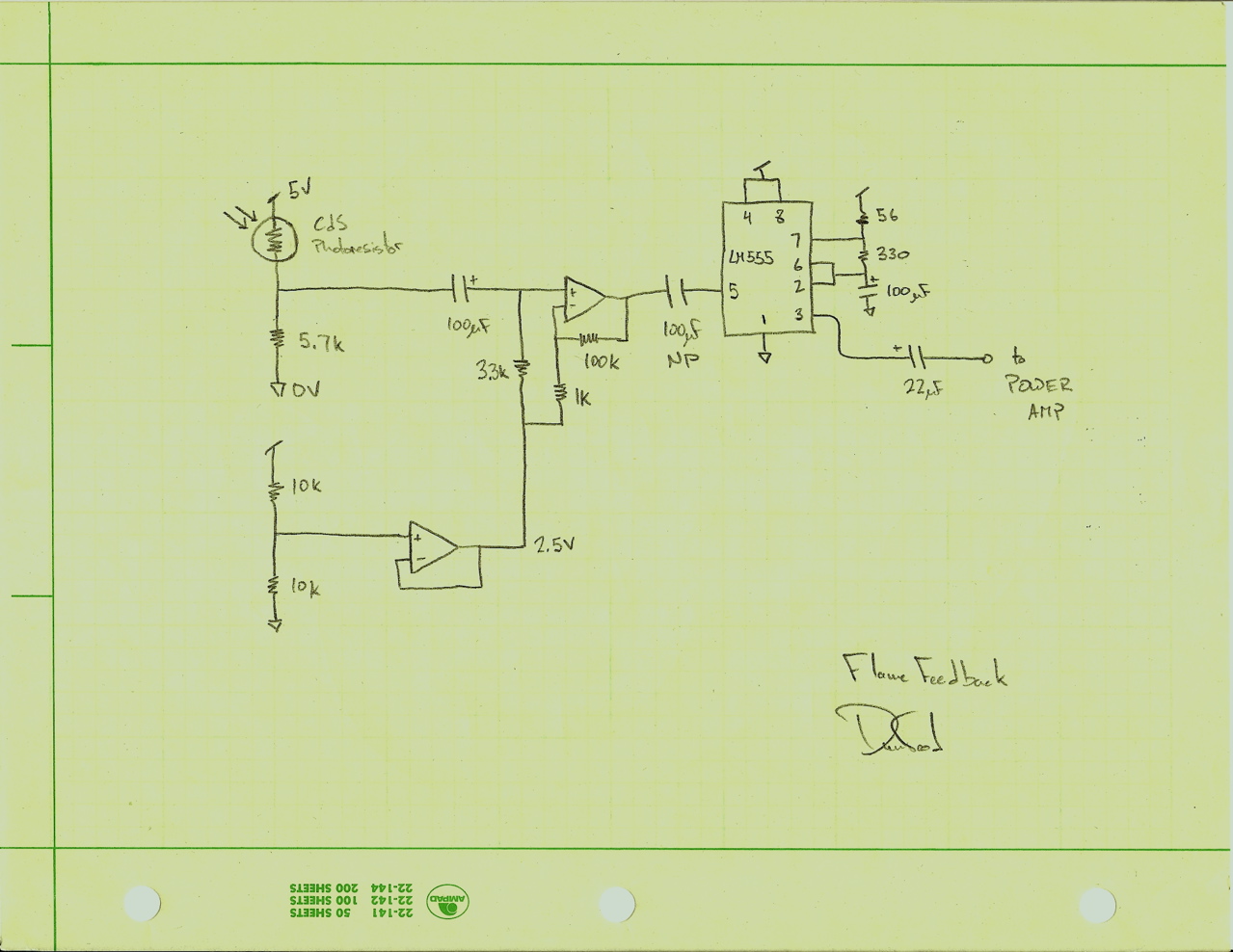
Flame Feedback
Flame Feedback is a sound sculpture constructed from a speaker driver, a candle, and electronic components. The speaker is activated with a low-frequency tone, which moves air and causes the candle to flicker. An optical sensor detects the flicker of...

Speaker to microphone converter circuit
This circuit provides a straightforward method for converting a loudspeaker into a microphone. When sound waves impact the diaphragm of the speaker, fluctuations occur in the coil, generating a small induced voltage that is typically low in magnitude and not...