


led strip Using a N-Mosfet to switch a common cathode ledstrip
#LED strip
#N-MOSFET
#common cathode
#switching circuit
#VCC
#STP50N06FI
#logic control
#lighting control

Description: A Common Cathode LED strip is being utilized instead of a Common Anode variant, leading to the development of a modified circuit. The experience with FETs was limited, resulting in challenges as a minimum voltage equal to Vcc is required to saturate the MOSFET. The circuit involves a VCC + STP50N06FI N-MOSFET with a 5V PWM signal controlling the brightness of the LED strip, which is connected to the common cathode. The ground is established through the circuit design.
In this circuit, a Common Cathode LED strip is employed, and the control of brightness is achieved using a Pulse Width Modulation (PWM) signal at 5V. The STP50N06FI N-channel MOSFET is selected for its capability to handle the current requirements of the LED strip.
To implement this circuit effectively, the MOSFET gate must be driven by a PWM signal from a microcontroller or similar device. The source of the MOSFET is connected to the ground, while the drain is connected to the negative terminal of the LED strip. The positive terminal of the LED strip is connected to the power supply (Vcc).
For proper operation, the PWM signal should be configured to switch between 0V and 5V, allowing the MOSFET to turn on and off rapidly. When the gate receives a high signal (5V), the MOSFET enters saturation, allowing current to flow through the LED strip, thereby illuminating it. Conversely, when the gate signal is low (0V), the MOSFET turns off, cutting off the current and turning off the LEDs.
To ensure the MOSFET operates correctly, it is essential to include a pull-down resistor on the gate to prevent floating states when the PWM signal is not active. A typical value for this resistor can range from 10kΩ to 100kΩ. Additionally, a flyback diode may be implemented across the LED strip to protect the MOSFET from voltage spikes generated by the inductive load when the LEDs are turned off.
This configuration allows for effective dimming of the LED strip by varying the duty cycle of the PWM signal, thus controlling the average power delivered to the LEDs and achieving the desired brightness levels. It is crucial to verify that the MOSFET's specifications, including the maximum current and voltage ratings, are suitable for the application to prevent component failure.As I am using a Common Cathode led-strip instead of a Common Anode one as used in the above link thus I came up with this `modified circuit`. Because my experience with FETs was nihil this didn`t actually work as I would need at least a voltage => Vcc to saturate the MOSFET.
VCC + STP50N06FI | N-MOSFET | |-+ _ |<- | \_-|-+ |_/ | Logic 5V (PWM) | Ledstrip V -> (Common - Cathode) | | = GND (created by AACircuit v1. 28. 6 beta 04/19/05 Is it possible to use a N-channel MOSFET at all for this application and if so, what do I need to do to make this work (Control the LED-strip brightness with a PWM signal, logic 5v).
In this circuit, a Common Cathode LED strip is employed, and the control of brightness is achieved using a Pulse Width Modulation (PWM) signal at 5V. The STP50N06FI N-channel MOSFET is selected for its capability to handle the current requirements of the LED strip.
To implement this circuit effectively, the MOSFET gate must be driven by a PWM signal from a microcontroller or similar device. The source of the MOSFET is connected to the ground, while the drain is connected to the negative terminal of the LED strip. The positive terminal of the LED strip is connected to the power supply (Vcc).
For proper operation, the PWM signal should be configured to switch between 0V and 5V, allowing the MOSFET to turn on and off rapidly. When the gate receives a high signal (5V), the MOSFET enters saturation, allowing current to flow through the LED strip, thereby illuminating it. Conversely, when the gate signal is low (0V), the MOSFET turns off, cutting off the current and turning off the LEDs.
To ensure the MOSFET operates correctly, it is essential to include a pull-down resistor on the gate to prevent floating states when the PWM signal is not active. A typical value for this resistor can range from 10kΩ to 100kΩ. Additionally, a flyback diode may be implemented across the LED strip to protect the MOSFET from voltage spikes generated by the inductive load when the LEDs are turned off.
This configuration allows for effective dimming of the LED strip by varying the duty cycle of the PWM signal, thus controlling the average power delivered to the LEDs and achieving the desired brightness levels. It is crucial to verify that the MOSFET's specifications, including the maximum current and voltage ratings, are suitable for the application to prevent component failure.As I am using a Common Cathode led-strip instead of a Common Anode one as used in the above link thus I came up with this `modified circuit`. Because my experience with FETs was nihil this didn`t actually work as I would need at least a voltage => Vcc to saturate the MOSFET.
VCC + STP50N06FI | N-MOSFET | |-+ _ |<- | \_-|-+ |_/ | Logic 5V (PWM) | Ledstrip V -> (Common - Cathode) | | = GND (created by AACircuit v1. 28. 6 beta 04/19/05 Is it possible to use a N-channel MOSFET at all for this application and if so, what do I need to do to make this work (Control the LED-strip brightness with a PWM signal, logic 5v).

Power Supply Circuit
The circuit comprises an N-MOSFET voltage follower (T1, common drain) and a current source (T2, NPN Darlington). The current source is set to 2.2 Amps. With a supply voltage of 40V, the circuit can deliver approximately 17W into an 8...

The PCS Scenemaster
The PCS SceneMaster Model LM4LS2 was awarded "Best Web Site" by Home Automator Magazine and was installed in the spring of 1999. This controller can ramp lights on and off and create "scenes," where a single X-10 command can generate...

Twelve road lighting control circuits
The adjustment potentiometer RP can modify the sensitivity of the device. Capacitors C1 function as an anti-light interference mechanism for instantaneous action.
The adjustment potentiometer (RP) is a variable resistor that allows for fine-tuning of the device's sensitivity. By altering the...

mosfet Driving LED strip from microcontroller
A strip of LEDs is controlled by a microcontroller using pulse-width modulation (PWM) to adjust brightness. The LED strip requires approximately 1.5A at 12V. The user, who has experience only with low-power digital electronics, seeks confirmation of their assumptions and...

Complementary lighting control
This lighting control unit will gradually decrease the brightness of one lamp while simultaneously increasing the brightness of another. The two loads maintain precise tracking without the need for manual adjustments. The gate of SCR1, a silicon-controlled rectifier, is activated...

Lighting auto controller
The following governor is designed to regulate the light intensity of a 220 V incandescent lamp. The circuit consists of relatively few components, allowing for easy assembly on a small circuit board. It is recommended to enclose the completed assembly...

lights 5GM168 control circuit diagram
Family karaoke lighting design incorporates various methods for circuit control. The control circuit described here features a four-way light output with loop jumping and speed control capabilities. A microphone detects the acoustic signal strength, allowing the lights to jump faster...
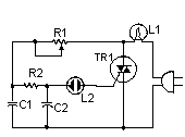
300-350W Lighting Control
This circuit illustrates a lighting control circuit diagram with a power rating of approximately 300-350W. Features include low cost, simplicity, and operation at 120V AC voltages. Components: ..
The lighting control circuit designed for 300-350W applications is intended to provide a...

LED strip meter circuit diagram of a point
A simple level power meter designed to provide a high-fidelity sound system with a bar or dot matrix display. The green LED display indicates levels from 0 to 7; level 8 is shown in yellow, and level 9 is indicated...