


LES produced using blackout emergency lighting
#emergency lighting
#power outage
#blackout
#LED
#backup power
#safety
#healthcare
#automatic switching
#battery backup
#illumination

Description: The circuit operation principle of the device illustrated in Figure 11 addresses the frequent occurrence of power outages, particularly in critical situations where continuous power supply is essential, such as during surgeries. The circuit employs a simple design that is fully automated. When 220V AC is present, lamp H1 illuminates, and the output from the LSE is at a high level, causing transistor VT to become inactive, which results in relay J being released and lamp H2 remaining off. In the event of a power outage, H1 turns off, the output from the LSE drops to a low level, leading to the conduction of transistor VT. This action activates relay J, which in turn powers lamp H2, allowing for an automatic transition between the two lamps during power interruptions.
The described circuit is a critical power management system designed to ensure continuous lighting during power failures. The primary components include a light source (H1), a backup light (H2), a relay (J), and a transistor (VT) which acts as a switch. The LSE (Light Sensing Element) monitors the AC power supply status. Under normal operating conditions, when the 220V AC supply is stable, H1 serves as the primary light source, illuminating the area. The high output from the LSE keeps the transistor VT in the off state, preventing the relay from engaging and keeping H2 turned off.
Upon detecting a power outage, the LSE output drops, triggering the conduction of transistor VT. This change activates relay J, which connects the power supply to lamp H2, thereby illuminating it as a backup light source. This automatic switching mechanism ensures that there is minimal disruption in lighting, which is particularly vital in environments requiring constant illumination, such as medical facilities.
The circuit's design emphasizes reliability and simplicity, ensuring that the transition between H1 and H2 is seamless, thereby providing a practical solution to power interruption challenges. The use of a relay for switching between light sources allows for a robust method of maintaining lighting without the need for manual intervention. This automated system is particularly beneficial in critical applications, enhancing safety and operational efficiency during unexpected power outages. Circuit operation principle of the device shown in Figure 11. Power outages are frequent thing, but some occasions, the power does not allow (such as the ongoing surgery, etc.) . LSE with simple circuit design, fully automated. When 220V AC, the lamp H1 lights up, while the LSE feet high output, transistor VT end, the relay J is released, it does not shine direct light H2. Once a power outage, H1 off, LSEs pin output low, then transistor VT conduction, the relay J pull, turn the power lights H2, H2 light automatically convert between almost two lights interruption.
The described circuit is a critical power management system designed to ensure continuous lighting during power failures. The primary components include a light source (H1), a backup light (H2), a relay (J), and a transistor (VT) which acts as a switch. The LSE (Light Sensing Element) monitors the AC power supply status. Under normal operating conditions, when the 220V AC supply is stable, H1 serves as the primary light source, illuminating the area. The high output from the LSE keeps the transistor VT in the off state, preventing the relay from engaging and keeping H2 turned off.
Upon detecting a power outage, the LSE output drops, triggering the conduction of transistor VT. This change activates relay J, which connects the power supply to lamp H2, thereby illuminating it as a backup light source. This automatic switching mechanism ensures that there is minimal disruption in lighting, which is particularly vital in environments requiring constant illumination, such as medical facilities.
The circuit's design emphasizes reliability and simplicity, ensuring that the transition between H1 and H2 is seamless, thereby providing a practical solution to power interruption challenges. The use of a relay for switching between light sources allows for a robust method of maintaining lighting without the need for manual intervention. This automated system is particularly beneficial in critical applications, enhancing safety and operational efficiency during unexpected power outages. Circuit operation principle of the device shown in Figure 11. Power outages are frequent thing, but some occasions, the power does not allow (such as the ongoing surgery, etc.) . LSE with simple circuit design, fully automated. When 220V AC, the lamp H1 lights up, while the LSE feet high output, transistor VT end, the relay J is released, it does not shine direct light H2. Once a power outage, H1 off, LSEs pin output low, then transistor VT conduction, the relay J pull, turn the power lights H2, H2 light automatically convert between almost two lights interruption.
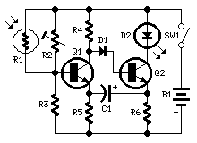
Dark-activated LED or Lamp Flasher
This circuit adopts the rather unusual Bowes/White emitter coupled multivibrator circuit. The oscillation frequency is about 1Hz and is set by C1 value. The LED starts flashing when the photo resistor is scarcely illuminated. The onset of flashing can be...

Nite Rider LEDS
As a keen cyclist I am always looking for ways to be seen at night. I wanted something that was a novelty and would catch the motorists eye. So looking around at my fellow cyclists rear lights, I came up...
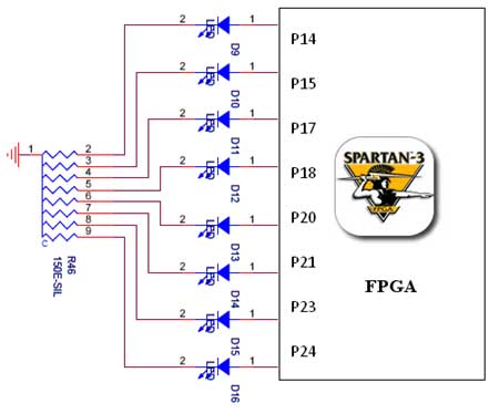
led interfacing with spartan 3 primer
The Spartan-3 board features eight LEDs connected to FPGA I/O pins, with the cathode of each LED connected to ground through a 330-ohm resistor. To illuminate a specific LED, the corresponding FPGA control signal must be driven to a high...

led How can I effectively reduce the voltage needed to activate a transistor
A circuit connects the line output (audio output) of a music-playing device to a large strip of approximately 200 LEDs, allowing them to flash in sync with the music. The circuit functions effectively when using a laptop as the audio...

10 LED VU meter LM3915
This simple LED VU meter has only a few parts but is useful as an indicator for the noise. The circuit is built around an LM3915, the brother of the logarithmic LM3914. The input signal from the VU meter is...

Key Illuminator Circuit
Used as a 10-second momentary illuminator, this circuit can be useful in other applications as well. Pressing SI charges CI, which holds Q1 on and keeps the LED lit for about 10 seconds.
The circuit described functions as a momentary illuminator,...

Knightrider lights for model cars
This simple circuit drives 6 LEDs in Knightrider scanner mode. Power consumption depends mainly on the type of LEDs used if you use a 7555 (555 CMOS version). More: Note that VDD and GND for the ICs are not shown...

White LED Head Lamp
This is a practical white LED head mount lamp (flashlight). Recently many white LED flashlights appear on the market. However, most flashlights require three cells because they are regulating output current with only series resistor. The odd number of cells...

ALPHANUMERIC LED DISPLAY PROJECT
A tiny sandwich flag connected perpendicular to the motor spindle aids observation of how long it takes to complete one full rotation. This worked initially, as each burst from the capacitor barely moved the flag 1/4 of a rotation. As...