


Light Sequencer Circuit
#light sequencer
#555 timer
#4017 Johnson counter
#SCR
#astable multivibrator
#clock pulses
#AC sequencer
#resistor
#capacitor

Description: The light sequencer employs two integrated circuits (ICs) and ten silicon-controlled rectifiers (SCRs) to create an alternating current (AC) sequencer. The first IC, a 555 timer, is configured as an astable multivibrator to generate clock pulses for the second IC. The output of the 555 timer is available on pin 3. The frequency of the clock pulses is controlled by capacitors C1 and C4, along with resistor R2 and potentiometer P1. The second IC, a 4017 Johnson counter, sequentially shifts a high signal to each of its ten output pins. Each output pin is connected to the gate lead of an SCR through resistive coupling. When the corresponding output pin of the 4017 is high and the positive half of the AC cycle is present at the anode lead of the SCR, the SCR is triggered and allows current to flow, illuminating the connected lamp. Power is supplied to the printed circuit (PC) board via a line cord, and the circuit incorporates a fuse for protection. Diode LD1 converts the AC to pulsating DC, which is then smoothed by capacitors C2 and C3. Resistor R23 limits the current, while zener diode D2 restricts the DC voltage to 6 VDC.
The light sequencer circuit operates by utilizing the timing capabilities of the 555 timer, which is set up in an astable mode. This configuration allows for continuous oscillation, generating a square wave output that serves as a clock signal. The frequency of this square wave is adjustable, providing flexibility in the timing of the light sequencing. The capacitors and resistor in conjunction with the potentiometer allow for fine-tuning of the pulse width and frequency, enabling the user to customize the light display according to their requirements.
The 4017 Johnson counter is a decade counter that counts from 0 to 9. It provides a high output on one of its ten pins sequentially with each clock pulse received from the 555 timer. This sequential output is essential for controlling the SCRs, as each SCR corresponds to a specific output pin on the 4017. The resistive coupling between the output pins and the SCR gates ensures that the SCRs are triggered appropriately, allowing for the controlled illumination of the connected lamp.
The inclusion of a fuse in the power supply circuit is a critical safety feature, protecting the circuit from overcurrent conditions that could lead to damage. The conversion of AC to pulsating DC by diode LD1 is crucial for the operation of the SCRs, which require a specific polarity to conduct. The smoothing capacitors C2 and C3 help to reduce the ripple in the pulsating DC, providing a more stable voltage for the subsequent stages of the circuit.
Resistor R23 plays an important role in current limiting, ensuring that the SCRs are not subjected to excessive gate current, which could lead to failure. The zener diode D2 serves as a voltage regulator, maintaining a consistent output voltage of 6 VDC, which is important for protecting sensitive components in the circuit from voltage spikes. Overall, this light sequencer design effectively combines timing, control, and safety features to create a functional and reliable lighting sequence. The light sequencer uses two ICs and 10 SCRs to create.an ac sequencer. The first 10, a 555 timer, is used to provide clock pulses for 102. The 10 is configured as an astable multivibrator, and its output is on pin 3. Capacitors CI and 04, along with resistor R2 and potentiometer PI, control the frequency of the pulses. IC2 is a 4017 Johnson counter, which shifts a high-signal level to each one of its 10 output pins in sequence.
Each output pin is resistively coupled to the gate lead an an SCR. When the respective output pin on the 4017 is high and the positive half of the ac cycle is on the anode lead of the SCR, it turns on. The lamp that is connected to its anode lights. Power is brought into the PC board by the line cord, then the circuit is fuse-protected. Diode LD1 changes the ac to pulsating, which is smoothed by C2 and C3. R23 limits the current, and zener diode D2 limits the dc voltage to 6 Vdc.
The light sequencer circuit operates by utilizing the timing capabilities of the 555 timer, which is set up in an astable mode. This configuration allows for continuous oscillation, generating a square wave output that serves as a clock signal. The frequency of this square wave is adjustable, providing flexibility in the timing of the light sequencing. The capacitors and resistor in conjunction with the potentiometer allow for fine-tuning of the pulse width and frequency, enabling the user to customize the light display according to their requirements.
The 4017 Johnson counter is a decade counter that counts from 0 to 9. It provides a high output on one of its ten pins sequentially with each clock pulse received from the 555 timer. This sequential output is essential for controlling the SCRs, as each SCR corresponds to a specific output pin on the 4017. The resistive coupling between the output pins and the SCR gates ensures that the SCRs are triggered appropriately, allowing for the controlled illumination of the connected lamp.
The inclusion of a fuse in the power supply circuit is a critical safety feature, protecting the circuit from overcurrent conditions that could lead to damage. The conversion of AC to pulsating DC by diode LD1 is crucial for the operation of the SCRs, which require a specific polarity to conduct. The smoothing capacitors C2 and C3 help to reduce the ripple in the pulsating DC, providing a more stable voltage for the subsequent stages of the circuit.
Resistor R23 plays an important role in current limiting, ensuring that the SCRs are not subjected to excessive gate current, which could lead to failure. The zener diode D2 serves as a voltage regulator, maintaining a consistent output voltage of 6 VDC, which is important for protecting sensitive components in the circuit from voltage spikes. Overall, this light sequencer design effectively combines timing, control, and safety features to create a functional and reliable lighting sequence. The light sequencer uses two ICs and 10 SCRs to create.an ac sequencer. The first 10, a 555 timer, is used to provide clock pulses for 102. The 10 is configured as an astable multivibrator, and its output is on pin 3. Capacitors CI and 04, along with resistor R2 and potentiometer PI, control the frequency of the pulses. IC2 is a 4017 Johnson counter, which shifts a high-signal level to each one of its 10 output pins in sequence.
Each output pin is resistively coupled to the gate lead an an SCR. When the respective output pin on the 4017 is high and the positive half of the ac cycle is on the anode lead of the SCR, it turns on. The lamp that is connected to its anode lights. Power is brought into the PC board by the line cord, then the circuit is fuse-protected. Diode LD1 changes the ac to pulsating, which is smoothed by C2 and C3. R23 limits the current, and zener diode D2 limits the dc voltage to 6 Vdc.

Nature simulator with 555 circuit
The circuit operates using an integrated circuit (IC) NE555 along with resistors R, RP, and capacitor C3, forming an astable multivibrator configuration. The output from pin 3 of the IC generates a square wave oscillation signal, which is passed through...

555 stepper pulse generator
The 555 Stepper Pulse Generator kit will help you with the pulse required to drive your favorite DC Servo Motor application. This kit uses the famous 555 timer IC for generating the Stepping Pulse. More: Input - 5 - 12...
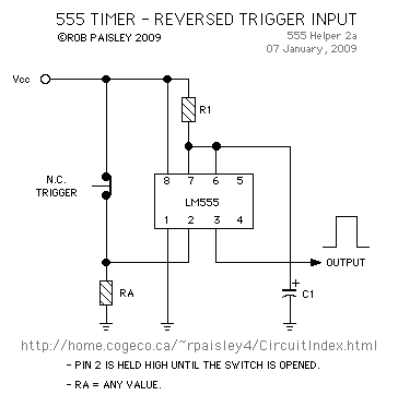
Schematic Diagram Trigger Input Control Of 555 Timers
The following method allows the timer to be triggered by a normally closed switch. This would be useful in applications such as intrusion alarms where the protection circuit is broken if a window or door is opened. Trigger Input Control...

LED Light Sequencer using 555
This project utilizes a 555 integrated circuit (IC) to create a sequential LED flashing effect. The configuration allows the LEDs to illuminate in a specific order, making it suitable for use as an indicator for vehicles and bicycles when turning...

Electronic Siren
This circuit produces a sound similar to a factory siren. It makes use of a 555 timer IC used as an astable multivibrator of a center frequency of about 300Hz. The frequency is controlled by pin 5 of the IC....

Extend Timer Range For The 555
Anyone who has designed circuits using the 555 timer chip has, at some point, wished for the ability to program longer timing periods. Timing intervals exceeding a few minutes are challenging to achieve due to the significant impact of component...

Voltage Controlled Switch with 555
The old and omnipresent NE555 can be very good at something it was not meant for: driving relays or other loads up to 200 mA. The picture shows an example circuit: if the input level rises over 2/3 of the...

Motion Activated On/Off Light or Electronic Appliance Schematic
The schematic is provided below. It is recommended to construct it in three distinct sections, similar to the method demonstrated. The 555 timer circuit: connect pin 2 to pin...
The schematic outlines a circuit design utilizing a 555 timer, a versatile...

555 Rock lantern controller circuit diagram
The controller features a buck rectifier circuit utilizing a 555 multivibrator, designed for controlling approximately 220V, 5W low-power parallel lights or 6 to 12V small bulb series. The 555 timer, along with components D3, D4, RP1, and C2, forms an...