


LM339 Using for LED VU Meter
#LM339
#LED
#VU meter
#voltage comparator
#audio level indicator
#volume meter
#voltage divider
#8 LEDs

Description: This circuit utilizes two quad voltage comparators, specifically the IC LM339, to illuminate a series of eight LEDs that indicate volume levels. Each of the eight comparators is biased at increasing voltages set by a voltage divider, allowing the lower right LED to activate first when the input reaches approximately 400 millivolts, which corresponds to about 22 milliwatts in an 8-ohm system. The divider voltages are configured so that each LED represents approximately twice the power level of the preceding one, resulting in a scale that extends from 22 milliwatts to about 2.5 watts when all LEDs are illuminated. Sensitivity can be adjusted with an input control to accommodate higher levels.
This circuit employs the LM339 quad voltage comparator, which contains four independent comparators capable of operating from a single power supply. The comparators are used to compare the input voltage, derived from an audio signal, against reference voltages set by a resistor voltage divider. The configuration ensures that as the input voltage increases, the corresponding LED lights up in sequence, providing a visual representation of the audio power levels.
The voltage divider consists of precision resistors that create reference voltages at predetermined levels. The first comparator is set to activate at 400 mV, illuminating the first LED. Subsequent comparators are set to activate at approximately 800 mV, 1.6 V, 3.2 V, and so forth, doubling the voltage threshold for each subsequent LED. This results in a clear and linear visual indication of power levels, making it easy to monitor audio output.
The circuit can be powered by a standard DC supply, typically ranging from 5 to 15 volts, depending on the application requirements. The output of each comparator is connected to an LED through a current-limiting resistor to prevent excessive current flow, ensuring the longevity of the LEDs. An additional input control can be incorporated to adjust the sensitivity of the circuit, allowing it to function effectively across a range of input levels without distortion or clipping.
Overall, this LED volume level indicator circuit provides an intuitive and effective means of visualizing audio power levels, making it a valuable tool for audio engineers and hobbyists alike. Proper testing and calibration are recommended to ensure accuracy and reliability in various operating conditions.This circuit in below uses two quad voltage comparator using IC LM339 to illuminate a series of 8 LEDs indicating volume level. Each of the 8 comparators is biased at increasing voltages set by the voltage divider so that the lower right LED comes on first when the input is about 400 mili volts or about 22 mili watt peaks in an 8 ohm system.
The d ivider voltages are set so that each LED represents about twice the power level as the one before so the scale extends from 22 mili watts to about 2. 5 watts when all LEDs are lit. The sensitivity can be decreased with the input control to read higher levels. I have not built or tested this circuit, so please let me know if you have problems getting it working.
This is the power levels should be as follows:
This circuit employs the LM339 quad voltage comparator, which contains four independent comparators capable of operating from a single power supply. The comparators are used to compare the input voltage, derived from an audio signal, against reference voltages set by a resistor voltage divider. The configuration ensures that as the input voltage increases, the corresponding LED lights up in sequence, providing a visual representation of the audio power levels.
The voltage divider consists of precision resistors that create reference voltages at predetermined levels. The first comparator is set to activate at 400 mV, illuminating the first LED. Subsequent comparators are set to activate at approximately 800 mV, 1.6 V, 3.2 V, and so forth, doubling the voltage threshold for each subsequent LED. This results in a clear and linear visual indication of power levels, making it easy to monitor audio output.
The circuit can be powered by a standard DC supply, typically ranging from 5 to 15 volts, depending on the application requirements. The output of each comparator is connected to an LED through a current-limiting resistor to prevent excessive current flow, ensuring the longevity of the LEDs. An additional input control can be incorporated to adjust the sensitivity of the circuit, allowing it to function effectively across a range of input levels without distortion or clipping.
Overall, this LED volume level indicator circuit provides an intuitive and effective means of visualizing audio power levels, making it a valuable tool for audio engineers and hobbyists alike. Proper testing and calibration are recommended to ensure accuracy and reliability in various operating conditions.This circuit in below uses two quad voltage comparator using IC LM339 to illuminate a series of 8 LEDs indicating volume level. Each of the 8 comparators is biased at increasing voltages set by the voltage divider so that the lower right LED comes on first when the input is about 400 mili volts or about 22 mili watt peaks in an 8 ohm system.
The d ivider voltages are set so that each LED represents about twice the power level as the one before so the scale extends from 22 mili watts to about 2. 5 watts when all LEDs are lit. The sensitivity can be decreased with the input control to read higher levels. I have not built or tested this circuit, so please let me know if you have problems getting it working.
This is the power levels should be as follows:
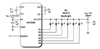
Drive Two-Six White LEDs (WLEDs) in Parallel
The parallel arrangement of LED backlights allows the control IC to utilize inexpensive low voltage CMOS processes, as illustrated in the following circuit diagram, which requires two to six white LEDs (WLEDs) in parallel. In many applications, LED backlights are...
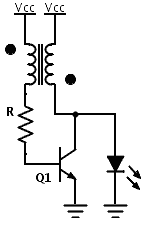
LED Boost converter Joule Thief circuit
Previously, a boost circuit was tested that enables the powering of a 3 V LED using a discharged battery (approximately 1 V or lower). This circuit consists of a single transistor, one resistor, and a small transformer with a 1:1...

High-intensity LED Warning Flasher
This circuit is designed as a warning flasher to alert road users to dangerous situations in low-light conditions. It can also function as a bicycle light, adhering to traffic regulations. White LEDs are recommended for use as a front bicycle...

flashingLEDs
Several individuals have requested clarification on calculating resistor values for a triac circuit. This information may be beneficial for adapting the Sous Vader for custom builds. The circuit in question involves the resistor values R1 and R2 in an optoisolator,...
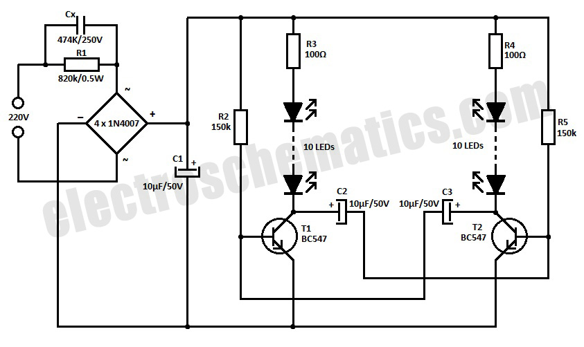
220V LED Blinker Circuit
This is a simple LED blinker or flasher designed for decorative purposes. The circuit features 20 high-brightness LEDs that flash alternately, creating a vibrant color display.
The LED blinker circuit typically consists of several key components including a microcontroller or timer...

USB Blinky
Projects often involve numerous LEDs and microcontrollers; however, there is appreciation for simpler implementations using LEDs. One of the most basic LED circuits is...
A basic LED circuit can be constructed using a single LED, a current-limiting resistor, and a power...

LED Audio VU Meter
This project is also an essential part of the expandable analyser to be published soon or perhaps eventually, and one meter circuit is used for each frequency band. There are many other uses for a simple LED VU meter. They...

A simple LED lamp circuit from scrap. Uses 5 LED and takes only 50 mA
Convert a used CFL into a power-saving LED lamp circuit that consumes only 50mA. This gadget can be used in applications like a night light, table lamp, etc.
The project involves redesigning a compact fluorescent lamp (CFL) to function as an...
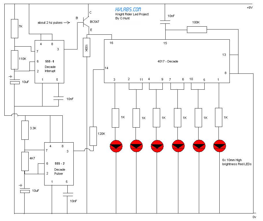
Authentic Looking Knight Rider Led Project
The circuit features red lights that chase up and down on the front of the kit, with a pause of about one second between each sequence. Unlike other circuits that continuously pulse a decade counter, this design employs two 555...