


Multi-point control corridor lights circuit
#corridor lights
#multi-point control
#button switches
#lighting control
#home automation
#electrical circuits
#light switch
#EL lights
#transformer

Description: Control buttons SB1 to SB4 can be installed in various positions within a corridor. By pressing any one of these buttons, the EL horse lights will turn on. After releasing the button, the transformer and rectifier supply power to the integrated circuit 555. The 555 integrated circuit has a 220µF capacitor connected to its first pin, which initially has a voltage of zero. When the first pin of the 555 IC outputs a high signal, relay K is activated, closing its normally open contact and putting the entire circuit into a self-locking timing state. Subsequently, the capacitor begins to charge through the first pin of the 555 IC. Once the capacitor's voltage reaches approximately 2/3 of the DC supply voltage, which takes about 3 minutes, the output of the 555 IC toggles to a low state, causing relay K to release and disconnecting the switch, turning off the EL lamp. Pressing any of the buttons SB1 to SB4 again will restart the timing sequence and turn the lights back on.
The described circuit employs a 555 timer IC configured in monostable mode to control the lighting system with a self-timer functionality. The control buttons SB1 through SB4 serve as momentary switches that trigger the circuit. When any button is pressed, it sends a signal to the 555 timer, initiating the timing sequence.
The transformer and rectifier convert the AC supply voltage into a suitable DC voltage for the circuit. The 220µF capacitor acts as a timing element, determining the duration for which the lights remain on after the button is released. The timing period is defined by the formula T = 1.1 * R * C, where R is the resistance in ohms connected to the timing circuit and C is the capacitance in farads. In this case, the capacitor is pre-charged to zero volts, and as the capacitor charges, the voltage across it rises until it reaches approximately 2/3 of the supply voltage, at which point the 555 timer output transitions low.
Relay K plays a crucial role in controlling the power to the EL horse lights. Its normally open contact allows current to flow to the lights when the relay is activated, turning them on. Once the timing period elapses, the relay deactivates, interrupting the power supply to the lights, which subsequently turn off.
This circuit design allows for flexible placement of control buttons throughout a corridor, enhancing user convenience while ensuring that the lighting system operates efficiently. The use of a 555 timer IC provides reliable timing control, making the circuit suitable for various applications where temporary lighting activation is desired.Control button switches SB1-SB4 can be installed in different positions corridor, just move SB1 ~ SB4 any one button, lights EL horse lights on, and after decompression transfo rmer, rectifier, to supply the integrated circuit 555. 555 integrated circuits, feet have connected 220yF initial capacitor voltage is zero, in an integrated circuit 555 is the first feet high output, relay K puff actuated, the normally open contact K is closed, the entire circuit into the timing of the self-locking status. Since then the power of the first integrated circuit 555, feet charge the capacitor voltage rises. When the electric charge container about 2/3 of the DC supply voltage to the timing between, about 3min.
In this case 555 integrated circuits pin output toggles low, so K release, contact switch K automatically disconnected, lamp EL off. Just then press SB1-SB4 any of a button, the forks will re-timing lights turned on.
The described circuit employs a 555 timer IC configured in monostable mode to control the lighting system with a self-timer functionality. The control buttons SB1 through SB4 serve as momentary switches that trigger the circuit. When any button is pressed, it sends a signal to the 555 timer, initiating the timing sequence.
The transformer and rectifier convert the AC supply voltage into a suitable DC voltage for the circuit. The 220µF capacitor acts as a timing element, determining the duration for which the lights remain on after the button is released. The timing period is defined by the formula T = 1.1 * R * C, where R is the resistance in ohms connected to the timing circuit and C is the capacitance in farads. In this case, the capacitor is pre-charged to zero volts, and as the capacitor charges, the voltage across it rises until it reaches approximately 2/3 of the supply voltage, at which point the 555 timer output transitions low.
Relay K plays a crucial role in controlling the power to the EL horse lights. Its normally open contact allows current to flow to the lights when the relay is activated, turning them on. Once the timing period elapses, the relay deactivates, interrupting the power supply to the lights, which subsequently turn off.
This circuit design allows for flexible placement of control buttons throughout a corridor, enhancing user convenience while ensuring that the lighting system operates efficiently. The use of a 555 timer IC provides reliable timing control, making the circuit suitable for various applications where temporary lighting activation is desired.Control button switches SB1-SB4 can be installed in different positions corridor, just move SB1 ~ SB4 any one button, lights EL horse lights on, and after decompression transfo rmer, rectifier, to supply the integrated circuit 555. 555 integrated circuits, feet have connected 220yF initial capacitor voltage is zero, in an integrated circuit 555 is the first feet high output, relay K puff actuated, the normally open contact K is closed, the entire circuit into the timing of the self-locking status. Since then the power of the first integrated circuit 555, feet charge the capacitor voltage rises. When the electric charge container about 2/3 of the DC supply voltage to the timing between, about 3min.
In this case 555 integrated circuits pin output toggles low, so K release, contact switch K automatically disconnected, lamp EL off. Just then press SB1-SB4 any of a button, the forks will re-timing lights turned on.

EI30 Transformer board
Every DAC board and decoder includes a power supply component. The only missing part is the power transformer. A toroidal transformer can be utilized, featuring a power switch and fuse holder mounted on the chassis. This document presents one of...
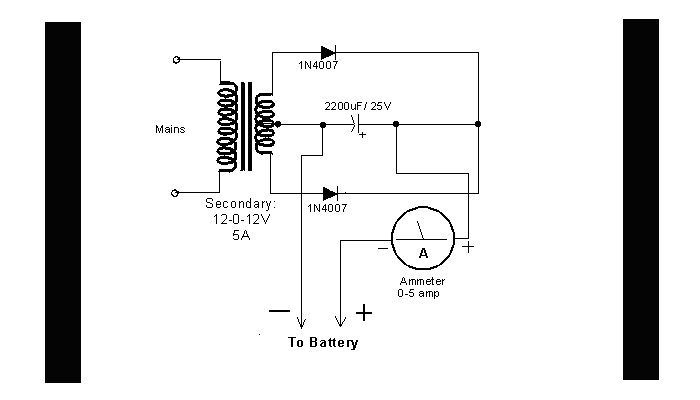
DIY Circuit Car Battery Charger
This simple circuit consists of a transformer, two diodes, a capacitor, and an ammeter. To charge a battery, connect the positive and negative terminals of the circuit to the corresponding terminals of the battery. When the battery is not charged,...

power supply am farm radio
The ability accumulation is a Tamura 3FD-410 5V bifold primary/dual accessory transformer, available from DigiKey.com at reasonable prices. The transformer's primary windings can be configured in series for 240VAC operation or in parallel for 120VAC operation. This configuration utilizes one...

Open and Short Circuit Test on Transformer
Open and short circuit tests on a transformer are conducted to determine the equivalent circuit of the transformer, assess its voltage regulation, and evaluate its efficiency.
The open circuit test is performed by applying the rated voltage to the primary winding...

High-rise residential walkway lighting control circuit
Pressing the button switch Sl-Sn activates the circuit, turning on the transformer T. The low-voltage alternating current from the secondary winding is directed to a bridge rectifier and a filter capacitor Ci, which produces a DC voltage. This voltage energizes...
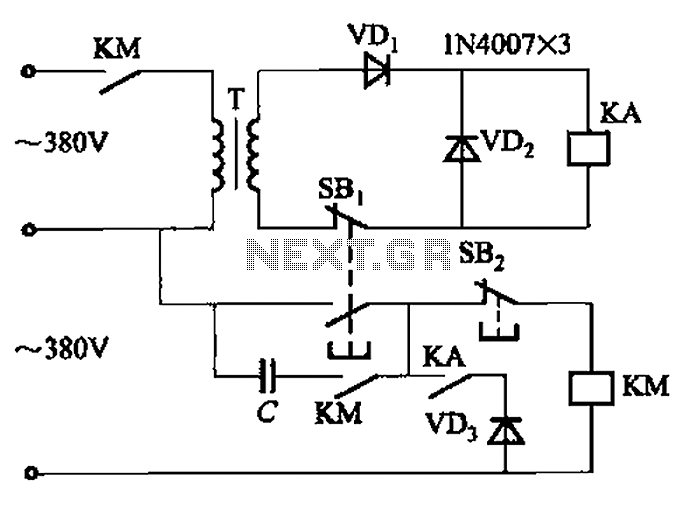
Transformer AC contactor DC operation circuit b
The AC contactor DC transformer circuit operates using various types of transformers and AC contactors in a DC application.
The AC contactor DC transformer circuit is designed to control and manage electrical power in applications where alternating current (AC) is converted...

Light Switch
Light Switch. This is a light switch or light-activated relay circuit. The relay activates when the light-dependent resistor (LDR) is uncovered and deactivates when the LDR is covered. It is adjustable for sensitivity and includes an LED indicator.
This light-activated relay...
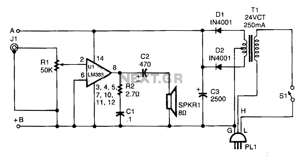
Line-operated-amplifier
T1 isolates the unit from the line and has a 24-V, center-tapped secondary. The output of the transformer is rectified by diodes D1 and D2 and filtered by capacitor C3 to provide 15 to 18 Vdc. The LM383 has built-in...

Classic car battery charging circuit diagram
The circuit operates after a transformer, utilizing a bridge rectifier and conditioning for battery charging. The charging current transformer can be easily adjusted to provide approximately 12V at 100Ah battery charging. The required charging current is 10A, and a 150VA...