


NC visible laser modulation driver circuit
#laser
#modulation
#driver circuit
#photodiode
#optical power
#NC visible laser
#laser tube
#light intensity
#slow response
#track modulation

Description: The laser tube drive circuit typically incorporates a photodiode that generates a laser beam proportional to the intensity (optical power) of the current. However, this type of photocell is generally slow and unable to track modulation effectively, particularly for peak light laser tube power. Consequently, this drive circuit monitors the average optical power to control the laser generator. The visible laser modulation driver circuit includes a digital-to-analog converter (DAC) with a 3-wire serial interface, which is used to maintain a constant average optical power output from the visible light laser tube. Additionally, there is a separate digital input line (MOD) and an open-drain output from a comparator (IC4) and transistor (VT1), which deliver pulses to the laser diode (VD1) for digital communications.
The laser tube drive circuit is designed to ensure stable operation of the laser system by continuously monitoring and adjusting the optical power output. The use of a photodiode allows for the detection of the laser beam intensity, providing feedback for the control system. However, due to the slow response time of the photodiode, it is not suitable for applications requiring rapid modulation of the laser output.
To address this limitation, the design incorporates a digital-to-analog converter (DAC) that translates digital signals into analog control voltages, thereby enabling precise adjustments to the laser power. The 3-wire serial interface facilitates communication between the DAC and the controlling microcontroller or digital signal processor, allowing for seamless integration into automated systems.
The visible laser modulation driver circuit is equipped with a separate digital input line (MOD) that can be used to trigger modulation events. The comparator (IC4) serves to compare the feedback signal from the photodiode with a reference voltage, ensuring that the output remains within specified limits. The open-drain output configuration allows for flexibility in interfacing with various components, including the transistor (VT1) that acts as a switch to pulse the laser diode (VD1) based on the digital commands received.
This architecture not only enhances the performance of the laser tube drive circuit but also allows for effective digital communication, making it suitable for applications in laser marking, engraving, and other industrial processes where precise control of laser output is crucial. The overall design emphasizes stability, responsiveness, and adaptability to varying operational demands.In the laser tube drive circuit are often provided with a photodiode, which generates a laser beam is proportional to the intensity (optical power) of the current, but in response to this type of photocell mostly relatively slow, generally can not track modulation peak light laser tube power. Therefore, this drive circuit is achieved by monitoring the average optical power to control the laser generator. NC visible laser modulation driver circuit is shown, which includes a digital to analog converter 10 3-wire serial interface (DAC), a visible light laser tube is used to control the output of a constant average optical power; a separate digital input line (MOD), an open-drain output by a comparator (IC4) and VTl, is fed to the laser diode VD1 pulse, digital communications.
The laser tube drive circuit is designed to ensure stable operation of the laser system by continuously monitoring and adjusting the optical power output. The use of a photodiode allows for the detection of the laser beam intensity, providing feedback for the control system. However, due to the slow response time of the photodiode, it is not suitable for applications requiring rapid modulation of the laser output.
To address this limitation, the design incorporates a digital-to-analog converter (DAC) that translates digital signals into analog control voltages, thereby enabling precise adjustments to the laser power. The 3-wire serial interface facilitates communication between the DAC and the controlling microcontroller or digital signal processor, allowing for seamless integration into automated systems.
The visible laser modulation driver circuit is equipped with a separate digital input line (MOD) that can be used to trigger modulation events. The comparator (IC4) serves to compare the feedback signal from the photodiode with a reference voltage, ensuring that the output remains within specified limits. The open-drain output configuration allows for flexibility in interfacing with various components, including the transistor (VT1) that acts as a switch to pulse the laser diode (VD1) based on the digital commands received.
This architecture not only enhances the performance of the laser tube drive circuit but also allows for effective digital communication, making it suitable for applications in laser marking, engraving, and other industrial processes where precise control of laser output is crucial. The overall design emphasizes stability, responsiveness, and adaptability to varying operational demands.In the laser tube drive circuit are often provided with a photodiode, which generates a laser beam is proportional to the intensity (optical power) of the current, but in response to this type of photocell mostly relatively slow, generally can not track modulation peak light laser tube power. Therefore, this drive circuit is achieved by monitoring the average optical power to control the laser generator. NC visible laser modulation driver circuit is shown, which includes a digital to analog converter 10 3-wire serial interface (DAC), a visible light laser tube is used to control the output of a constant average optical power; a separate digital input line (MOD), an open-drain output by a comparator (IC4) and VTl, is fed to the laser diode VD1 pulse, digital communications.

Laser Power Supplies
Construct universal power supplies, including low-voltage power supplies for operating electronic equipment. The designs include single- and dual-voltage regulated supplies, an all-purpose adjustable version, and battery pack regulators. A helium-neon laser tube requires a high-voltage power supply for operation.
There...

Modulated Light DX
Which type of modulated light receiver should be used? A photodiode directly connected to a high-gain, high-impedance amplifier; a photodiode connected to a current amplifier; a back-biased photodiode; FET input or bipolar IC or discrete components? How can noise be...

Precision photodiode comparator
Rl sets the comparison level. At comparison, the photodiode has less than 5 mV across it, decreasing dark current by an order of magnitude. More: IC = LM 111/211/311.
In this circuit description, the resistor Rl plays a crucial role in...

Precision photodiode level detector
The output state changes at a photodiode current of 0 µA. For R1 = 2 MΩ, R2 = R3 = 5 MΩ.
The described circuit likely involves a photodiode used in conjunction with resistors R1, R2, and R3 to create a...

Photodiode signal conditioner
The specified photodiode exhibits a linear response to light intensity across a 100 dB range. To digitize the diode's linearly amplified output, an A-D converter with a range of 17 bits would be necessary. However, this requirement can be circumvented...

automatic laser poweroff circuit
Here is the automatic laser power-off circuit schematic. This circuit features a visible power indication. In this case, the ground is connected on one side.
The automatic laser power-off circuit is designed to enhance safety and efficiency in laser applications by...
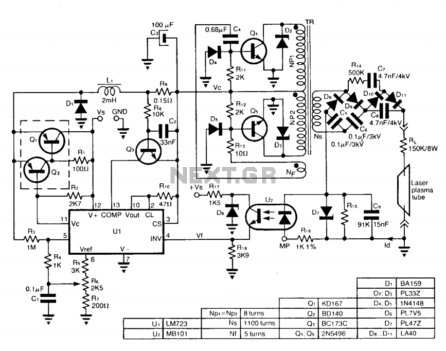
Stabilizing a laser discharge current
The circuit employs a free-running push-pull DC to DC high voltage converter to generate the required voltage for the laser plasma tube supply. The supply voltage (Vc) of this converter is regulated by a switch-mode power supply to maintain a...

Home-Built Pulsed Multiple Gas (PMG) Laser
The Pulsed Multiple Gas (PMG) laser discussed in this chapter shares several similarities with the Home-Built Pulsed Argon and/or Krypton (Ar/Kr) Ion Laser featured in Scientific American. However, the PMG laser has also been utilized with xenon (Xe) and oxygen...

laser DPSS
This document outlines the transformation of a basic, cost-effective green laser pointer into a laboratory-grade laser. The core of this diode-pumped solid-state (DPSS) laser is an affordable green laser pointer. These pointers are essentially DPSS lasers that include a small...