


New RGB Backlighting System for Liquid Crystal Display
#RGB LED
#optical sensor
#feedback controller
#color stability
#brightness control
#LCD backlighting
#temperature compensation
#lighting system

Description: The system utilizes RGB LED light sources, an optical sensor, and a feedback controller. The purpose of employing optical feedback is to ensure color stability over temperature variations, maintain constant brightness, and control any specific color point or brightness required by the LCDs. The article includes sections discussing the main functional blocks of the backlighting system, understanding of xy coordinates and brightness (colorimetry), Luxeon RGB light sources, typical LED performance concerning temperature and lifetime behavior, LED output wavelength using pulse width modulation (PWM), a description of the RGB backlighting system, feedback controller aspects (clipping, brightness, calibration), photodiode sensor usage for averaging radiometric power, and details on Luxeon LED drivers. The capabilities of a high-performance LED backlight system for LCDs using optical feedback and Luxeon light sources for color control are explored in the referenced LCD article.
The described system integrates multiple components to achieve a sophisticated backlighting solution for LCD displays. The RGB LED light sources are critical for generating a wide spectrum of colors, which are essential for high-quality visual output. The optical sensor plays a pivotal role in monitoring the emitted light, allowing for real-time adjustments to maintain color accuracy and brightness consistency.
The feedback controller is designed to process the data from the optical sensor, enabling it to make necessary adjustments based on temperature fluctuations and other environmental factors. This ensures that the color output remains stable, regardless of external conditions. The feedback mechanism may involve clipping techniques to prevent oversaturation of colors and calibration processes to align the output with desired standards.
Understanding colorimetry within this context is vital, as it involves the measurement of color in terms of its xy coordinates and brightness levels. This knowledge aids in fine-tuning the system to achieve precise color representation. The incorporation of pulse width modulation (PWM) allows for efficient control of LED brightness, providing a dynamic range that can adapt to varying display requirements.
In addition, the performance characteristics of the Luxeon RGB light sources are examined, particularly their behavior concerning temperature changes and their longevity, which are crucial for ensuring the reliability of the backlighting system over time. The output wavelength of the LEDs is also a significant factor, as it influences the overall color quality delivered to the LCD.
The integration of a photodiode sensor enhances the system's ability to average the radiometric power, providing feedback that is essential for maintaining optimal performance. The Luxeon LED drivers are responsible for powering the LEDs and ensuring they operate within their specified parameters, contributing to the overall efficiency and effectiveness of the backlighting solution.
This comprehensive approach to backlighting not only improves the visual experience of LCD displays but also enhances the longevity and reliability of the lighting system through careful monitoring and control mechanisms.utilize RGB LED lightsources, an optical sensor and feedback controller. The aim of using optical feedback is a color stability over temperature, maintaining constant brightness, and controlling any color point or brightness required by the LCDs. Within the article you will find section discuss about Main functional blocks of the backlighting syst
ems, The understanding of xy coordinate and brightness y (colorimetry), Luxeon RGB lightsource, Typical LED performance in temperature/lifetime behaviour, LED output wavelength using pulse width modulation (PWM), the RGB backlighting system description (click figure to enlarge), Feedback controller (clipping, brightness, calibration), Photodiode sensor for averaging radiometric power, and Luxeon LED driver descriptions. See the capability of high performanceLED backlight systemfor LCDsusing optical feedback and luxeon lightsources for color controlling in the following LCD article (source: philipslumileds.
com).
The described system integrates multiple components to achieve a sophisticated backlighting solution for LCD displays. The RGB LED light sources are critical for generating a wide spectrum of colors, which are essential for high-quality visual output. The optical sensor plays a pivotal role in monitoring the emitted light, allowing for real-time adjustments to maintain color accuracy and brightness consistency.
The feedback controller is designed to process the data from the optical sensor, enabling it to make necessary adjustments based on temperature fluctuations and other environmental factors. This ensures that the color output remains stable, regardless of external conditions. The feedback mechanism may involve clipping techniques to prevent oversaturation of colors and calibration processes to align the output with desired standards.
Understanding colorimetry within this context is vital, as it involves the measurement of color in terms of its xy coordinates and brightness levels. This knowledge aids in fine-tuning the system to achieve precise color representation. The incorporation of pulse width modulation (PWM) allows for efficient control of LED brightness, providing a dynamic range that can adapt to varying display requirements.
In addition, the performance characteristics of the Luxeon RGB light sources are examined, particularly their behavior concerning temperature changes and their longevity, which are crucial for ensuring the reliability of the backlighting system over time. The output wavelength of the LEDs is also a significant factor, as it influences the overall color quality delivered to the LCD.
The integration of a photodiode sensor enhances the system's ability to average the radiometric power, providing feedback that is essential for maintaining optimal performance. The Luxeon LED drivers are responsible for powering the LEDs and ensuring they operate within their specified parameters, contributing to the overall efficiency and effectiveness of the backlighting solution.
This comprehensive approach to backlighting not only improves the visual experience of LCD displays but also enhances the longevity and reliability of the lighting system through careful monitoring and control mechanisms.utilize RGB LED lightsources, an optical sensor and feedback controller. The aim of using optical feedback is a color stability over temperature, maintaining constant brightness, and controlling any color point or brightness required by the LCDs. Within the article you will find section discuss about Main functional blocks of the backlighting syst
ems, The understanding of xy coordinate and brightness y (colorimetry), Luxeon RGB lightsource, Typical LED performance in temperature/lifetime behaviour, LED output wavelength using pulse width modulation (PWM), the RGB backlighting system description (click figure to enlarge), Feedback controller (clipping, brightness, calibration), Photodiode sensor for averaging radiometric power, and Luxeon LED driver descriptions. See the capability of high performanceLED backlight systemfor LCDsusing optical feedback and luxeon lightsources for color controlling in the following LCD article (source: philipslumileds.
com).
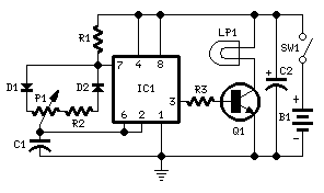
Brightness Control for small Lamps
Switch-mode driven 1.5V bulbs. This device was designed on request, to control the light intensity of four filament lamps (i.e. a ring illuminator) powered by two AA or AAA batteries, for close-up pictures with a digital camera. Obviously it can...
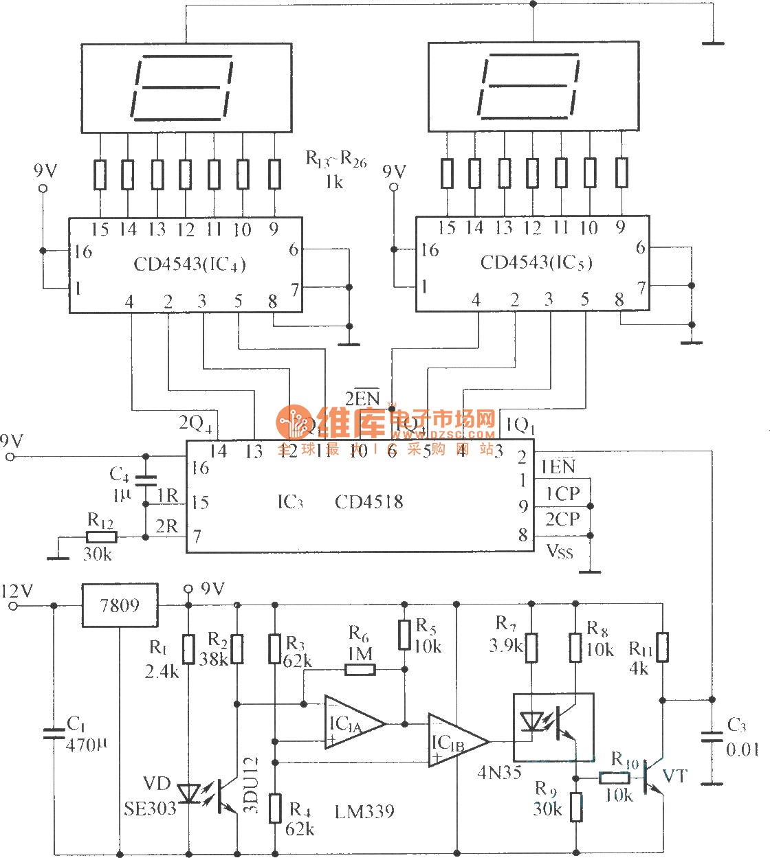
Digital displaying photoelectric counter circuit diagram
The circuit includes an optical input circuit (VD, 3DU12), a pulse forming circuit (IC1A, IC1B functioning as a voltage comparator; optical coupler; transistor switching circuit), and a counting and display circuit.
The circuit architecture consists of several key components that work...

Ambient-light-ignoring-sensor
A resonance-tuned narrow-band amplifier enhances the optical object detector's resistance to stray light. The components C1 and L1 within the feedback loop of IC2A enable the operational amplifier to transmit only those frequencies that are at or near the LED's...

pcb Help identifying and finding shematics/datasheets for circuit board
The chip in the center with small bullet holes is likely proprietary. It is possible to salvage a few components from it, although understanding the circuit is not necessary for this purpose. Additionally, it is confirmed that the device is...

Low loss brightness control
This circuit alters the average value of the DC supply voltage due to the high switching frequency. The tungsten lamp will exhibit an almost continuous adjustable light output ranging from 0 to 100%. If a light-emitting diode is utilized as...
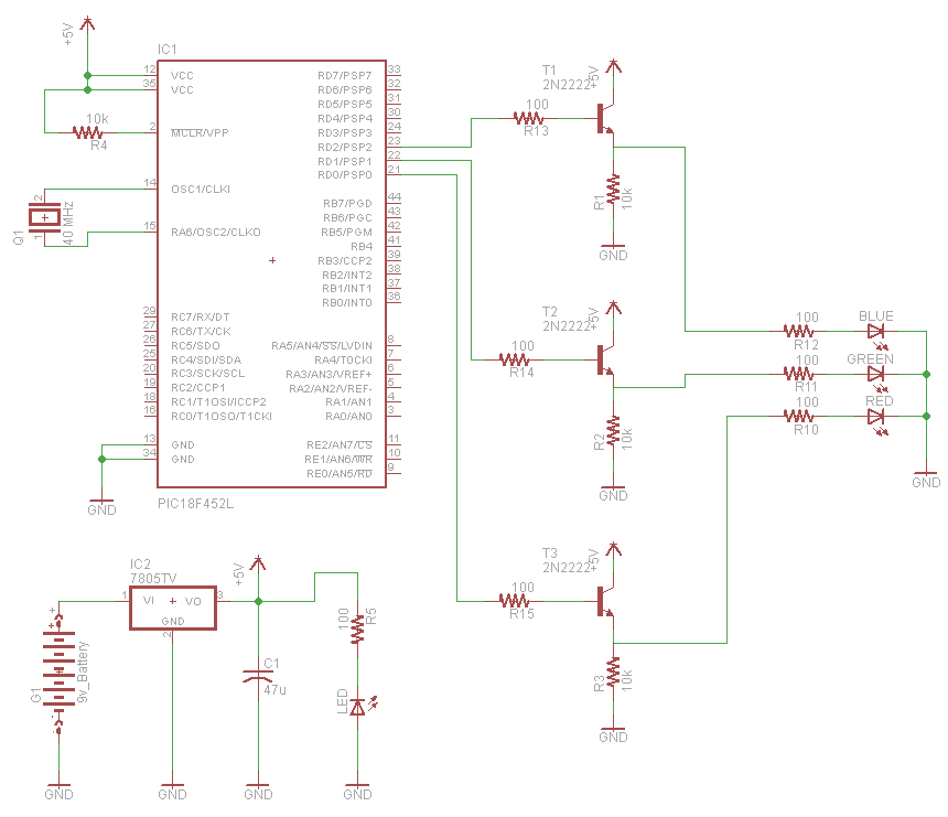
rgb led controller using pic18f452
A very popular type of LED that has finally emerged is the tri-color, RGB LED. The RGB stands for red, green, and blue, as the LED is capable of displaying various colors through the combination of these three primary colors.
The...

USB RGB LED VU Meter
This project creates an RGB LED VU Meter controlled via USB by a host machine running Windows 7 or Vista. It serves multiple purposes: it demonstrates the ability to read audio information from the Windows machine and transmit it over...

Drive an RGB led with software PWM
This project demonstrates the use of an ATTiny microcontroller and an RGB LED to create a light that continuously cycles through random colors, with the ability to change color dramatically at the press of a switch. The inspiration for this...

Circuit diagram of brightness control relay
This document presents a brightness control relay circuit. Resistors R1, R2, and R3 create a voltage divider circuit with a light-sensitive resistor. When the light level drops below a specific threshold, the base voltage of VT1 increases, causing VT1 and...