


One transistor LED Flasher
#LED
#flasher
#transistor
#2N2222
#negative resistance
#avalanche
#capacitor
#resistor
#simple circuit

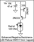
Description: This may be the simplest LED flasher circuit you can build, with the notable exclusion of LEDs with integrated flashing circuits. This might be a good replacement for the LM3909 in some applications. Take a close look. Only the emitter and collector leads of the 2N2222 are connected. The base lead was cut off. The LED is from a string of Christmas lights, and it has an integrated 100 Ohm resistor. This LED flasher occurred to me while reading about negative resistance in transistors. In this implementation, a common NPN transistor is used. In the circuit, a 1k resistor charged the 330 µF capacitor until the voltage became large enough to get the emitter-base junction to avalanche. If the resistor that charges the capacitor is too low in value (or if the power supply voltage is too high), the current through the transistor will not become low enough for the transistor to turn off. If the resistor that charges the capacitor is too high in value (or the power supply voltage is too low), the capacitor will not be able to charge to a high enough voltage to enable the transistor to turn on. This is because the transistor draws a small amount of current before switching on. In the oscilloscope image, it can be seen that the peak voltage (yellow trace) was a little bit less than 9 volts. At this point, the transistor turned on quickly and partially discharged the 330 µF capacitor through the LED and the 100 Ohm current limiting resistor. The current waveform, which is the voltage drop across the 100 Ohm resistor, is shown in the blue trace on the scope image. Peak current was 26 milliamps, and the transistor continued to discharge the capacitor until conduction suddenly ceased at 6 milliamps (Many thanks to Luke in Australia for pointing out the correct current). After the transistor stopped conducting, the capacitor began charging again, thus starting a new cycle. I've tried this with red LEDs with and without integrated current limiting resistors, and on some white LEDs. This circuit can be built without the current limiting resistor, but if you choose to do so, please be aware that the peak currents may be high enough to shorten the life of the LED. The capacitor value isn't critical. A lower value will result in faster oscillation and shorter flashes. The 2N2222 NPN transistor seems to work reliably in this circuit. Other transistors may be more temperamental, and others might not work at all.
The LED flasher circuit described operates on a simple principle of charging and discharging a capacitor through a transistor. The 2N2222 NPN transistor is used in this circuit with its base lead removed, allowing for a direct connection between the emitter and collector. This configuration exploits the transistor's ability to switch on and off based on the voltage across the capacitor, which is charged through a 1kΩ resistor.
Initially, the 330 µF capacitor charges until the voltage reaches approximately 9 volts. At this threshold, the emitter-base junction of the transistor enters avalanche breakdown, causing the transistor to turn on rapidly. This results in the capacitor discharging through the LED and the 100 Ω current-limiting resistor, producing a flash of light. The current flowing through the circuit peaks at around 26 mA, as indicated by the oscilloscope measurements. Once the discharge current drops to 6 mA, the transistor turns off, halting the conduction and allowing the capacitor to recharge, thereby initiating a new cycle.
The choice of charging resistor is critical for the operation of the circuit. If the resistance is too low, the capacitor will charge too quickly, preventing the transistor from turning off. Conversely, if the resistance is too high, the capacitor may not charge sufficiently to turn the transistor on. The circuit can accommodate various LED types, including those with integrated resistors, but caution should be exercised regarding the peak current to avoid damaging the LED.
The oscillation frequency of the circuit can be adjusted by varying the capacitor's value; a smaller capacitor will yield faster oscillation and shorter flash durations. The 2N2222 transistor is noted for its reliability in this application, although other transistor types may exhibit unpredictable behavior. This LED flasher circuit represents a practical and simple approach to creating flashing LED effects, suitable for various applications.This may be the simplest LED flasher circuit you can build, with the notable exclusion of LED's with integrated flashing circuits. This might be a good replacement for the LM3909 in some applications. Take a close look. Only the emitter and collector leads of the 2N2222 are connected. The base lead was cut off. The LED is from a string of Christmas lights and it has an integrated 100 Ohm resistor. This LED flasher occurred to me while reading about negative resistance in transistors. In this implementation, a common NPN transistor is used. In the circuit, a 1k resistor charged the 330 uf capacitor until the voltage became large enough to get the emitter-base junction to avelanche.
If the resistor that charges the capacitor is too low in value (or if the power supply voltage is too high), the current through the transistor will not become low enough for the transistor to turn off. If the resistor that charges the capacitor is too high in value (or the power supply voltage is too low), the capacitor will not be able to charge to a high enough voltage to enable the transistor to turn on.
This is because the transistor draws as small amount of current before switching on. In the oscilloscope image, it can be seen that the peak voltage (yellow trace) was a little bit less than 9 volts. At this point transistor turned on quickly and partially discharged the 330 uf capacitor through the LED and the 100 Ohm current limiting resistor.
The current wavform, which is the voltage drop across the 100 Ohm resistor, is shown in the blue trace on the scope image. Peak current was 26 milliamps, and the transistor continued to discharge the capacitor until conduction suddenly ceased at 6 milliamps (Many thanks to Luke in Australia for pointing out the correct current).
After the transistor stopped conducting, the capacitor began charging again, thus starting a new cycle. I've tried this with red LED's with and without integrated current limiting resistors, and on some while LED's.
This circuit can be built without the current limiting resistor, but if you choose to do so, please be aware that the peak currents may be high enough to shorten the life of the LED. The capacitor value isn't critical. A lower value will result in faster oscillation and shorter flashes. The 2N2222 NPN transistor seems to work reliably in this circuit. Other transistors may be more tempermental, and others might not work at all.
The LED flasher circuit described operates on a simple principle of charging and discharging a capacitor through a transistor. The 2N2222 NPN transistor is used in this circuit with its base lead removed, allowing for a direct connection between the emitter and collector. This configuration exploits the transistor's ability to switch on and off based on the voltage across the capacitor, which is charged through a 1kΩ resistor.
Initially, the 330 µF capacitor charges until the voltage reaches approximately 9 volts. At this threshold, the emitter-base junction of the transistor enters avalanche breakdown, causing the transistor to turn on rapidly. This results in the capacitor discharging through the LED and the 100 Ω current-limiting resistor, producing a flash of light. The current flowing through the circuit peaks at around 26 mA, as indicated by the oscilloscope measurements. Once the discharge current drops to 6 mA, the transistor turns off, halting the conduction and allowing the capacitor to recharge, thereby initiating a new cycle.
The choice of charging resistor is critical for the operation of the circuit. If the resistance is too low, the capacitor will charge too quickly, preventing the transistor from turning off. Conversely, if the resistance is too high, the capacitor may not charge sufficiently to turn the transistor on. The circuit can accommodate various LED types, including those with integrated resistors, but caution should be exercised regarding the peak current to avoid damaging the LED.
The oscillation frequency of the circuit can be adjusted by varying the capacitor's value; a smaller capacitor will yield faster oscillation and shorter flash durations. The 2N2222 transistor is noted for its reliability in this application, although other transistor types may exhibit unpredictable behavior. This LED flasher circuit represents a practical and simple approach to creating flashing LED effects, suitable for various applications.This may be the simplest LED flasher circuit you can build, with the notable exclusion of LED's with integrated flashing circuits. This might be a good replacement for the LM3909 in some applications. Take a close look. Only the emitter and collector leads of the 2N2222 are connected. The base lead was cut off. The LED is from a string of Christmas lights and it has an integrated 100 Ohm resistor. This LED flasher occurred to me while reading about negative resistance in transistors. In this implementation, a common NPN transistor is used. In the circuit, a 1k resistor charged the 330 uf capacitor until the voltage became large enough to get the emitter-base junction to avelanche.
If the resistor that charges the capacitor is too low in value (or if the power supply voltage is too high), the current through the transistor will not become low enough for the transistor to turn off. If the resistor that charges the capacitor is too high in value (or the power supply voltage is too low), the capacitor will not be able to charge to a high enough voltage to enable the transistor to turn on.
This is because the transistor draws as small amount of current before switching on. In the oscilloscope image, it can be seen that the peak voltage (yellow trace) was a little bit less than 9 volts. At this point transistor turned on quickly and partially discharged the 330 uf capacitor through the LED and the 100 Ohm current limiting resistor.
The current wavform, which is the voltage drop across the 100 Ohm resistor, is shown in the blue trace on the scope image. Peak current was 26 milliamps, and the transistor continued to discharge the capacitor until conduction suddenly ceased at 6 milliamps (Many thanks to Luke in Australia for pointing out the correct current).
After the transistor stopped conducting, the capacitor began charging again, thus starting a new cycle. I've tried this with red LED's with and without integrated current limiting resistors, and on some while LED's.
This circuit can be built without the current limiting resistor, but if you choose to do so, please be aware that the peak currents may be high enough to shorten the life of the LED. The capacitor value isn't critical. A lower value will result in faster oscillation and shorter flashes. The 2N2222 NPN transistor seems to work reliably in this circuit. Other transistors may be more tempermental, and others might not work at all.

Transistor Tutorial Power Amplifiers Part 4
An audio power amplifier can enhance weak signals from devices like tuners, CD players, or tape decks to fill a room with sound. This article emphasizes the operating principles and circuitry of low-frequency power amplifiers utilizing bipolar junction transistors (BJTs)....

Motion sensing LED Quantum Bits
The circuit operates as follows: The LED is typically powered at a low brightness through resistors R1 and R3. SW1 functions as a spring and wire-based accelerometer. When SW1 is activated, capacitor C2 charges rapidly at a rate determined by...

Single Transistor Half-Wave Peak Detector Circuit
Using only a single transistor and a few passive components, a fairly sensitive peak detector circuit can be built. This peak detector circuit is suitable for various applications.
The peak detector circuit utilizes a single transistor, typically configured in a common-emitter...

28 led clock timer with 74hct circuit
This is a programmable alarm timer circuit that uses LEDs to indicate hours and minutes. Twelve LEDs can be arranged in a circle to represent the 12 hours of a clock face, and an additional 12 LEDs can be arranged...

Two Flashing LEDs Circuit
This circuit diagram illustrates a setup for two flashing LEDs designed for various applications, including model construction and recreational uses. It features adjustable flashing speeds controlled by two potentiometers. The circuit comprises a combination of active and passive components. It...
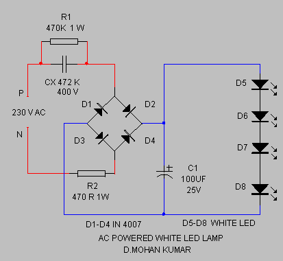
220V AC Powered White Led Lamp
The circuit provides sufficient illumination suitable for reading purposes. Capacitor CX, in conjunction with diodes D1 through D4, constitutes the AC step-down circuit. CX lowers the high voltage AC from the mains to a low voltage AC, which is subsequently...

led flasher circuit schematic inside
Build a circuit that will flash five pairs of LEDs at variable rates. To achieve this, a circuit utilizing five NE555 timers has been designed. Trim pots will be used to control the variable flash rate. Assistance is needed in...

LED light
The goal was to create a compact flashlight that could be held in the mouth, easily stored in a pocket, and positioned on a surface to project light upwards. The budget was set at approximately $15, which was significantly lower...

LED torch using NSI45090JDT4G constant current regulator
A very simple LED torch can be designed using the NSI45090JDT4G adjustable constant current regulator (CCR) from ON Semiconductor, utilizing very few external components. The NSI45090JDT4G device provides a cost-effective solution for regulating current in LEDs. This constant current regulator...