


Phone camera flash control circuit
#flash circuit
#charge pump
#AAT3110-4.5
#voltage boost
#lithium battery
#LED
#camera flash
#peak current
#regulated voltage

Description: A circuit designed for a phone photo camera flash that delivers a peak current of 200mA. It utilizes the AAT3110-4.5 capacitive charge pump chip to boost and regulate the lithium battery voltage to 4.5V. This voltage powers a series of light-emitting diodes (LEDs) that operate at a peak current ranging from 100mA to 200mA. The peak current flows through a switch, forming a loop that generates a flash. The circuit includes an input filter capacitor with a capacitance of 10µF, an output filter capacitor with a capacitance of 4.7µF, and a storage capacitor with a capacitance of 1µF. Resistor R1 serves as a balancing resistor for the LED light-emitting tubes, while resistor RP is used for peak current regulation; adjusting RP allows for setting the desired peak current.
The circuit operates on the principle of a capacitive charge pump, which is a type of DC-DC converter that steps up the input voltage to a higher output voltage using capacitors as energy storage elements. The AAT3110-4.5 chip is specifically designed for such applications, providing efficient voltage boosting while maintaining a compact design suitable for mobile devices.
In this application, the lithium battery, typically around 3.7V, is boosted to 4.5V, which is suitable for driving high-brightness LEDs. The output filter capacitor (4.7µF) smooths the output voltage, ensuring stable operation of the LEDs during the flash event. The storage capacitor (1µF) temporarily holds charge to provide the necessary current during the peak flash period.
Resistor R1 is crucial for balancing the current across multiple LEDs, ensuring uniform brightness and preventing any single LED from being overdriven, which could lead to premature failure. The peak current regulation resistor RP allows for fine-tuning of the flash intensity. By adjusting the resistance value of RP, the user can control the peak current flowing through the LEDs, thus adjusting the brightness of the flash according to specific requirements.
Overall, this circuit design is optimized for providing a reliable and adjustable flash for mobile phone cameras, enhancing low-light photography capabilities while ensuring efficient power management from the device's battery.200mA peak current letter phone photo camera flash circuit, using a AAT3110-4.5 electrical capacitive charge pump chip, the phone lithium battery voltage boost and regulated to 4.5V, to a group of light-emitting diode (LED) provide work for the voltage and 100 ~ 200mA peak current. The peak current through the switch as a flash of VF form a loop. The charge pump input filter capacitor capacitance of lOtiF, output filter capacitor electric capacity 4.
7vF, storage capacitor capacitance of ltiF. Ri, LED light-emitting tube balancing resistor. RP is the peak current regulation section resistance, adjust the resistance of RP can be set peak current size.
The circuit operates on the principle of a capacitive charge pump, which is a type of DC-DC converter that steps up the input voltage to a higher output voltage using capacitors as energy storage elements. The AAT3110-4.5 chip is specifically designed for such applications, providing efficient voltage boosting while maintaining a compact design suitable for mobile devices.
In this application, the lithium battery, typically around 3.7V, is boosted to 4.5V, which is suitable for driving high-brightness LEDs. The output filter capacitor (4.7µF) smooths the output voltage, ensuring stable operation of the LEDs during the flash event. The storage capacitor (1µF) temporarily holds charge to provide the necessary current during the peak flash period.
Resistor R1 is crucial for balancing the current across multiple LEDs, ensuring uniform brightness and preventing any single LED from being overdriven, which could lead to premature failure. The peak current regulation resistor RP allows for fine-tuning of the flash intensity. By adjusting the resistance value of RP, the user can control the peak current flowing through the LEDs, thus adjusting the brightness of the flash according to specific requirements.
Overall, this circuit design is optimized for providing a reliable and adjustable flash for mobile phone cameras, enhancing low-light photography capabilities while ensuring efficient power management from the device's battery.200mA peak current letter phone photo camera flash circuit, using a AAT3110-4.5 electrical capacitive charge pump chip, the phone lithium battery voltage boost and regulated to 4.5V, to a group of light-emitting diode (LED) provide work for the voltage and 100 ~ 200mA peak current. The peak current through the switch as a flash of VF form a loop. The charge pump input filter capacitor capacitance of lOtiF, output filter capacitor electric capacity 4.
7vF, storage capacitor capacitance of ltiF. Ri, LED light-emitting tube balancing resistor. RP is the peak current regulation section resistance, adjust the resistance of RP can be set peak current size.

Light Chaser I
Up to 100 lights, LEDs, or optocoupler triac circuits can be sequentially activated by this circuit. One (U1) 4017 decodes and sequences 10 LEDs, whose common anode is returned through a second (U2) CD4017, which counts at one-tenth of the...

Lithium Dry Battery Charger Five
The lithium battery charger introduced in the example can charge a 6V lithium-ion battery in a constant current mode and switch to constant voltage charge mode when the battery voltage reaches 4.1V.
The lithium battery charger circuit operates on a...

light up pumpkin
The concept involves placing a pair of yellow LEDs inside a pumpkin, combined with a photo sensor that activates the lights at night. The circuit is simple, utilizing minimal components. Two schematics are provided on the project site, with a...

10 LED Audio Amplifier Power-meter
This indicator lets you see how much power an amplifier produces. The circuit uses an LM 3915, the logarithmic variation of the known IC LED VU Meter LM 3914. The circuit is connected directly to the speaker output of amplifier...
Automotive LED Timing Light
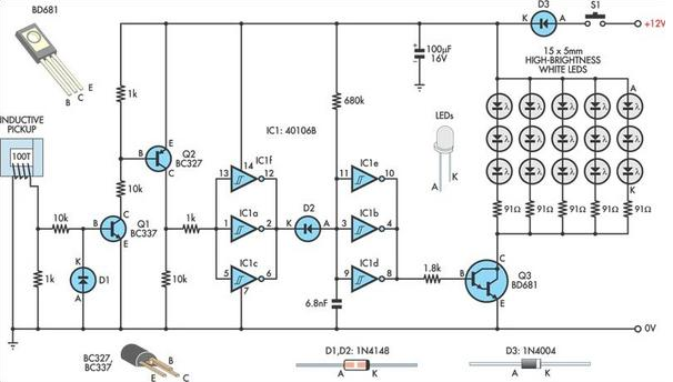
A useful timing strobe can be constructed using high-brightness LEDs and a few common components. Ignition pulses from the number 1 cylinder high-tension lead are used to trigger the circuit via a homemade inductive pickup. Transistors Q1 and Q2 buffer...
LED Flasher
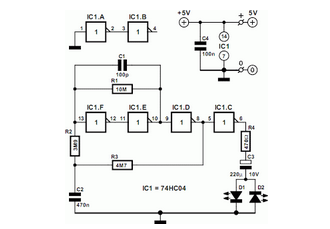
The concept of this cost-effective flashing LED indicator is straightforward: it utilizes a low-frequency oscillator to control two LEDs.
This flashing LED indicator circuit is designed to provide a visual signal using two light-emitting diodes (LEDs) that alternate in illumination. The...
Lamp pulser circuit
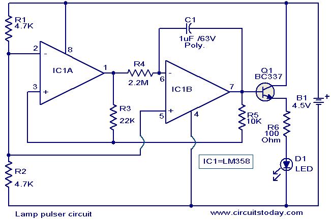
This circuit is designed to gradually pulse an LED or a low-power filament lamp, creating a visual effect where the light transitions from an OFF state to full brightness and then back down to OFF. Such a circuit is particularly...

72 led clock
The circuit utilizes 60 individual LEDs to represent the minutes of a clock and 12 LEDs to indicate the hours. The power supply and timing circuitry are consistent with those outlined in the previous 28 LED clock circuit. The minutes...
Drive Two-Six White LEDs (WLEDs) in Parallel
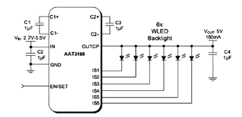
The parallel arrangement of LED backlights allows the control IC to utilize inexpensive low voltage CMOS processes, as illustrated in the following circuit diagram, which requires two to six white LEDs (WLEDs) in parallel. In many applications, LED backlights are...