


Photo Flash Slave Unit Circuit

Description: The phototransistor Q1 receives a light pulse from a photoflash unit. The pulse is AC-coupled to amplifier Q2, which subsequently triggers SCR1, activating a flash unit connected to J1.
The circuit begins with the phototransistor Q1, which is sensitive to light pulses emitted by a photoflash unit. When a light pulse is detected, Q1 conducts, allowing the signal to be AC-coupled to the base of the amplifier Q2. This coupling is typically achieved through a capacitor that blocks any DC component of the signal while allowing the AC pulse to pass through. The amplifier Q2 amplifies the received pulse, increasing its amplitude to a level sufficient to drive the next component in the circuit.
Following amplification, the output of Q2 is connected to the gate of SCR1 (Silicon Controlled Rectifier). The SCR is a semiconductor device that acts as a switch, allowing current to flow once it has been triggered. When Q2 outputs a sufficient voltage, it triggers SCR1, enabling it to conduct and complete the circuit to the connected flash unit.
The flash unit, which is connected to terminal J1, is activated by the current flowing through SCR1. This configuration allows for a rapid response to the incoming light pulse, facilitating the triggering of the flash unit in synchronization with the original light source. The overall design is commonly used in applications where quick and reliable light detection and response are necessary, such as in automatic photography or light-activated signaling systems. Phototransistor Ql receives a light pulse from a photoflash unit. The pulse is ac-coupled to amplifier Q2. It then triggers SCR1, which triggers a flash unit that is connected to Jl.
The circuit begins with the phototransistor Q1, which is sensitive to light pulses emitted by a photoflash unit. When a light pulse is detected, Q1 conducts, allowing the signal to be AC-coupled to the base of the amplifier Q2. This coupling is typically achieved through a capacitor that blocks any DC component of the signal while allowing the AC pulse to pass through. The amplifier Q2 amplifies the received pulse, increasing its amplitude to a level sufficient to drive the next component in the circuit.
Following amplification, the output of Q2 is connected to the gate of SCR1 (Silicon Controlled Rectifier). The SCR is a semiconductor device that acts as a switch, allowing current to flow once it has been triggered. When Q2 outputs a sufficient voltage, it triggers SCR1, enabling it to conduct and complete the circuit to the connected flash unit.
The flash unit, which is connected to terminal J1, is activated by the current flowing through SCR1. This configuration allows for a rapid response to the incoming light pulse, facilitating the triggering of the flash unit in synchronization with the original light source. The overall design is commonly used in applications where quick and reliable light detection and response are necessary, such as in automatic photography or light-activated signaling systems. Phototransistor Ql receives a light pulse from a photoflash unit. The pulse is ac-coupled to amplifier Q2. It then triggers SCR1, which triggers a flash unit that is connected to Jl.

Full-wave scr control
This circuit allows a single Silicon Controlled Rectifier (SCR) to control resistive loads in a full-wave configuration. Resistor R3 must be selected to ensure that when potentiometer R2 is set to its minimum value, the current flowing through the load...

Bassman Modifications
Upgrading to a 3-prong AC cord is a common modification, as is the replacement of filter capacitors. Switching coupling capacitors to brands like Orange Drops or other boutique options is also popular, often enhancing the appeal in online auctions. Additional...

phototransistor Light sensor using Photo Transistor
A circuit that uses a phototransistor to create a light-sensitive switch. When there is no light in the room, the LED connected to the phototransistor lights up, and when there is light, the LED turns off. Any schematic or circuit...

Simple SCR oscillator
Silicon controlled rectifiers (SCR) can easily oscillate if there is an inductor (a speaker coil in this case) which gives just enough extra voltage to completely switch off the sustain current. In this way a new cycle may start and...

zero voltage switching
The SCR coupler circuit offers increased sensitivity to input signals as demonstrated. This enables the utilization of the more economical 4N39 (H11C3) with the drive currents exceeding 7 mA provided by the input circuit.
The SCR coupler circuit is designed to...
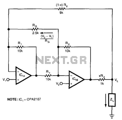
Bootstrapped Amp Current Source
This circuit responds to the difference between Vj and V2. Rq sets the gain. Resistors XR2 and (1 - X) R2 produce the bootstrap effect. These two resistors convert the circuit's output voltage to a current. IC1 and IC2 are...

Delayed Alarm Circuit
The alarm/sensor circuit is constructed using two SCRs, a transistor, a 4049 hex inverter, and several supporting components, which together create a closed-loop detection circuit featuring a delay mechanism. This delay allows entry into a protected area and deactivation of...

RF-AMP Documentation
The amplifier is suitable for various projects to buffer and amplify outputs from devices such as Direct Digital Synthesizer (DDS) chips. It was initially designed to amplify the output of the 9833 DDS chip and is also intended for Amateur...

Precision polarity switching circuit by conventional elements
The loop gain of the operational amplifier (OP) is primarily influenced by the ratio of the input resistor to the feedback resistor. Consequently, any resistance error can lead to a corresponding gain error, which necessitates the use of high-precision resistors,...