


Photo stop action
#stop-action
#photography
#sequential firing
#SCR
#timing circuit
#bulb control
#automated lighting
#photographic effects
#bouncing ball effect

Description: This circuit provides multiple "stop-action" photographic effects, such as capturing a bouncing ball in up to nine different positions within a single photograph. The circuit is designed to automatically activate the bulbs sequentially, with a variable time interval between each activation. It is functionally complete, with the exception of the actual firing mechanism. In many instances, a simple Silicon Controlled Rectifier (SCR) can be utilized, as illustrated. The firing process can be initiated in one of two ways: a trigger pulse can be applied to the trigger input terminal via a capacitor, or the unit can function as a slave device. Illumination from a camera-mounted flash will trigger the circuit through its integrated photocell pickup. The interval between each successive flash is determined by capacitor C1 and resistor R1, which are adjustable. After each activation, the circuit must be reset by briefly pressing the reset button.
This circuit is designed to facilitate advanced photographic techniques by enabling the capture of multiple images in rapid succession, effectively freezing motion for analysis or artistic effect. The sequential firing of bulbs is critical for achieving the desired stop-action effect. The use of an SCR as the firing mechanism allows for efficient control over the high current required to activate the bulbs, ensuring reliable operation.
The trigger input terminal serves as the primary control point, where an external trigger pulse can be introduced. This allows for flexibility in operation; when a capacitor is connected, it filters the pulse to ensure smooth activation. Alternatively, integrating a photocell pickup enables the circuit to respond to external light sources, such as a flash from a camera. This feature is particularly useful in dynamic shooting environments where the timing of the flash is crucial.
The timing of the bulb activations is adjustable, thanks to the combination of capacitor C1 and resistor R1. By varying these components, the user can modify the duration between each flash, allowing for tailored photographic effects. This adjustability is essential for different scenarios, such as capturing fast-moving objects or creating specific visual effects.
The reset mechanism is straightforward; a momentary press of the reset button clears the circuit's previous state, preparing it for the next series of activations. This ensures that the user can quickly and efficiently prepare the circuit for subsequent shots without significant downtime.
In summary, this circuit represents a versatile tool for photographers seeking to explore motion capture techniques. Its design incorporates essential features for flexibility, reliability, and ease of use, making it suitable for both amateur and professional applications in the realm of stop-action photography.This circuit gives multiple "stop-action" photographic effects like showing a bouncing ball in up to nine locations in a single photograph. The circuit will automatically fire the bulbs sequentially with the time between each firing variable.
The circuit is functionally complete except for the actual firing system. In many cases, a simple SCR will work, as shown. The firing can be initiated in one of two ways A trigger pulse can be applied to the trigger input terminal through a capacitor, or can operate the unit as a slave. Light from a. camera-mounted flash will activate the circuit through its built-in photocell pickup. The time period between each successive flash is determined by Cl and Rl, which is variable. After firing the circuit, it must be reset by momentarily depressing the reset button.
This circuit is designed to facilitate advanced photographic techniques by enabling the capture of multiple images in rapid succession, effectively freezing motion for analysis or artistic effect. The sequential firing of bulbs is critical for achieving the desired stop-action effect. The use of an SCR as the firing mechanism allows for efficient control over the high current required to activate the bulbs, ensuring reliable operation.
The trigger input terminal serves as the primary control point, where an external trigger pulse can be introduced. This allows for flexibility in operation; when a capacitor is connected, it filters the pulse to ensure smooth activation. Alternatively, integrating a photocell pickup enables the circuit to respond to external light sources, such as a flash from a camera. This feature is particularly useful in dynamic shooting environments where the timing of the flash is crucial.
The timing of the bulb activations is adjustable, thanks to the combination of capacitor C1 and resistor R1. By varying these components, the user can modify the duration between each flash, allowing for tailored photographic effects. This adjustability is essential for different scenarios, such as capturing fast-moving objects or creating specific visual effects.
The reset mechanism is straightforward; a momentary press of the reset button clears the circuit's previous state, preparing it for the next series of activations. This ensures that the user can quickly and efficiently prepare the circuit for subsequent shots without significant downtime.
In summary, this circuit represents a versatile tool for photographers seeking to explore motion capture techniques. Its design incorporates essential features for flexibility, reliability, and ease of use, making it suitable for both amateur and professional applications in the realm of stop-action photography.This circuit gives multiple "stop-action" photographic effects like showing a bouncing ball in up to nine locations in a single photograph. The circuit will automatically fire the bulbs sequentially with the time between each firing variable.
The circuit is functionally complete except for the actual firing system. In many cases, a simple SCR will work, as shown. The firing can be initiated in one of two ways A trigger pulse can be applied to the trigger input terminal through a capacitor, or can operate the unit as a slave. Light from a. camera-mounted flash will activate the circuit through its built-in photocell pickup. The time period between each successive flash is determined by Cl and Rl, which is variable. After firing the circuit, it must be reset by momentarily depressing the reset button.

SCR AC arc welding machine load path from one power outage circuit
The Triac V trigger voltage is less than 1V, and the trigger current is less than 30mA.
The Triac is a semiconductor device commonly used for controlling AC power. It operates by allowing current to flow in both directions when triggered,...
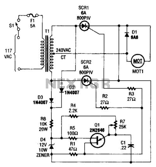
Speed-Control Switch Circuit Circuit
A center-tapped 240-V transformer is used with two SCR devices to provide rectified AC (pulsating DC) to MOT1. Q1 is a UJT ramp generator used to generate trigger pulses for SCR1 and SCR2.
The circuit employs a center-tapped transformer rated for...

SLAVE FLASH TRIGGER
The SCR is connected across the trigger circuit of the flash gun. In its normal state, the SCR remains off, allowing the flash gun to charge to its trigger voltage. A phototransistor, Q1, monitors the light level. When a high-intensity...

Fill light indoor photography circuit
Engaged in indoor portrait photography, practitioners often find that using a single camera can result in images lacking depth and layering. To achieve better photographic outcomes, multiple auxiliary lighting sources are typically arranged around the subject. The following describes a...

SCR UJI TIME DELAY
The timing interval is initiated by applying power and is determined by the resistor-capacitor (RT-CT) combination. At the end of the interval, a unijunction transistor triggers a silicon controlled rectifier (SCR) to apply nearly the full supply voltage to the...

An SCR Based Burglar Alarm - Adding Extra Zones
The SCR Burglar Alarm System allows for the addition of multiple extra zones. The primary circuit is designed for typical normally-closed input devices, including magnetic reed contacts, micro switches, foil tape, and passive infrared (PIR) sensors. An additional circuit includes...

thermostat for 1kw space heater scr controlled
The heating element is connected in series with two back-to-back 16 amp silicon-controlled rectifiers (SCRs), which are controlled by a small pulse transformer. This pulse transformer features three identical windings: two are dedicated to providing trigger pulses to the SCRs,...

SCR And Triac Triggering Circuit With A Positive Power Supply
The output current of the control circuit must be amplified when the gate current needed to trigger the device exceeds the output current of the control circuit.
To achieve the amplification of the control circuit output current, a suitable transistor configuration...

Scr Capacitor Turn-Off Circuit
After the SCR is activated, capacitor CI charges up to nearly the full supply voltage through resistor R3 and the anode of the SCR. When switch S2 is later closed, it grounds the positive terminal of CI, causing the charge...