


Porch Light Control Circuit
#porch light
#CDS photocell
#555 timer
#light control
#automatic switch
#timer circuit
#photocell sensor
#on/off cycle
#preset period
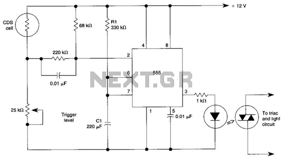
Description: This circuit can control the on/off cycle of a light using a CDS photocell and turn it off after a preset period. The light can only be activated when the CDS cell is in darkness, and it remains on for a duration determined by the 555 timer circuit. The on-time is influenced by resistor R1 and capacitor C1, and is approximately 80 seconds with the specified component values.
The described circuit utilizes a light-dependent resistor (CDS photocell) to detect ambient light levels. When the light intensity falls below a certain threshold, indicating darkness, the photocell allows current to flow, triggering the operation of the circuit. The heart of the timing function is the 555 timer IC, configured in monostable mode. In this configuration, the 555 timer generates a single output pulse when triggered, with the pulse duration defined by the resistor (R1) and capacitor (C1) values.
The relationship between R1, C1, and the output time (T) can be expressed by the formula T = 1.1 * R1 * C1. For instance, if R1 is set to a specific value in ohms and C1 is a capacitor measured in farads, the resulting time period can be calculated to achieve the desired on-time for the light. In this case, with the component values provided, the on-time is approximately 80 seconds.
To ensure proper functionality, the circuit should include a power supply compatible with the 555 timer IC and the light load. Additionally, a transistor or relay may be employed to switch the light on and off, depending on the current rating of the light source. The design must also incorporate protective elements such as diodes to prevent back EMF from inductive loads, ensuring the longevity and reliability of the circuit.
This circuit is ideal for applications such as outdoor lighting, where automatic control based on ambient light conditions can enhance energy efficiency and provide convenience. Proper layout and soldering techniques should be employed to minimize noise and ensure stable operation of the photocell and timer circuit. This circuit can control the on/off cycle of a light via a CDS photocell, and turn it off after a preset period. The light can only be turned on when CDS cell is in darkness, and it stays on for a time determined by the 555 circuit.
On time depends on R1 and CI and is about 80 seconds with the values shown.
The described circuit utilizes a light-dependent resistor (CDS photocell) to detect ambient light levels. When the light intensity falls below a certain threshold, indicating darkness, the photocell allows current to flow, triggering the operation of the circuit. The heart of the timing function is the 555 timer IC, configured in monostable mode. In this configuration, the 555 timer generates a single output pulse when triggered, with the pulse duration defined by the resistor (R1) and capacitor (C1) values.
The relationship between R1, C1, and the output time (T) can be expressed by the formula T = 1.1 * R1 * C1. For instance, if R1 is set to a specific value in ohms and C1 is a capacitor measured in farads, the resulting time period can be calculated to achieve the desired on-time for the light. In this case, with the component values provided, the on-time is approximately 80 seconds.
To ensure proper functionality, the circuit should include a power supply compatible with the 555 timer IC and the light load. Additionally, a transistor or relay may be employed to switch the light on and off, depending on the current rating of the light source. The design must also incorporate protective elements such as diodes to prevent back EMF from inductive loads, ensuring the longevity and reliability of the circuit.
This circuit is ideal for applications such as outdoor lighting, where automatic control based on ambient light conditions can enhance energy efficiency and provide convenience. Proper layout and soldering techniques should be employed to minimize noise and ensure stable operation of the photocell and timer circuit. This circuit can control the on/off cycle of a light via a CDS photocell, and turn it off after a preset period. The light can only be turned on when CDS cell is in darkness, and it stays on for a time determined by the 555 circuit.
On time depends on R1 and CI and is about 80 seconds with the values shown.

10 Minute Id Timer
Designed to automatically identify a transmitter every 10 minutes, this 555 circuit has adjustable charge and discharge paths. The IC should be a standard 555 type, not a CMOS type. C3 should be tantalum. The relay is a small 5-V...

police siren pcb
This circuit generates a sound akin to a police siren. It utilizes two 555 timer integrated circuits (ICs) configured as astable multivibrators. The frequency is regulated by pin 5 of the IC. The first IC operates at approximately 1Hz, where...

Tele Timer Circuit
The circuit is designed around a 555 oscillator/timer, providing two distinct time periods. The longer time period can be adjusted between approximately 1 to 10 minutes, while the shorter time period is fixed at around three seconds. The operation of...

A New Solar / Wind Charge Controller Based on the 555 Chip
The prototype was successfully assembled on a breadboard and subsequently built on a piece of Radio Shack protoboard for field use. The assembly process took only a couple of hours, and it functioned correctly on the first attempt. This more...

555 DC Voltage Doubler Circuit
This DC voltage doubler circuit generates a voltage that is double its supply voltage. It is advantageous when a higher voltage level is required from a single lower voltage power supply. Due to the low current consumption in such applications,...

555 Timer LED Flasher Circuit
All of the components in this list are generally available through RadioShack for less than $20. It is highly recommended to use a breadboard for assembly, as mistakes are common for first-time builders, and soldering can complicate troubleshooting. This tutorial...

Nixie low voltage PSU With 555 Timer IC
The following circuit illustrates a low voltage power supply (PSU) for Nixie tubes utilizing a 555 Timer integrated circuit (IC). The coil used in this schematic is purchased from a store.
The described circuit operates as a low voltage power supply...

Sequential Flasher
A 555 timer is used to drive a CMOS counter in this device, which employs an RCA CA3079 zero-voltage switch to control triacs TR1 through TR4. This circuit can be utilized for sequencing lamp displays, among other applications. Caution is...
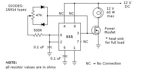
LIGHT DIMMER
The 555 timer light dimmer schematic circuit is shown in figure 1 below. For the light dimmer to work, the 555 timer is configured as a variable cycle astable oscillator running somewhere around 300 Hz. The power MOSFET used here...