


portable solar lantern circuit uses 6
#solar panel
#LED
#portable
#renewable energy
#6 volt
#5 watt
#photo-voltaic
#energy efficient
#battery powered
#outdoor lighting

Description: This portable solar lantern circuit utilizes a 6 volt/5 watt solar panel, which is widely available. With this photovoltaic panel, an economical, simple, yet efficient and truly portable solar lantern unit can be constructed. The next essential component required is a high-power (1 watt) white LED module. When the solar panel is adequately exposed to sunlight, approximately 9 volts DC can be obtained from the panel to recharge a 4.8 volt/600 mAh rated Ni-Cd battery pack. A red LED (D2) serves as a charging process indicator, assisted by resistor R1. Resistor R2 regulates the charging current flow to approximately 150 mA. Assuming a 4-5 hour sunlit day, the solar panel, with a 150 mA current set by the charge controller resistor R2, can transfer around 600-750 mAh into the battery pack. When power switch S1 is activated, the DC supply from the Ni-Cd battery pack is directed to the white LED (D3). Resistor R3 determines the current through the LED, while capacitor C1 acts as a buffer.
This portable solar lantern circuit is designed to harness solar energy efficiently, making it an ideal solution for outdoor lighting applications. The 6V/5W solar panel captures sunlight and converts it into electrical energy, generating about 9V DC under optimal conditions. This energy is used to charge a 4.8V Ni-Cd battery pack, which stores the energy for later use.
The charging process is indicated by the red LED (D2), which illuminates when the battery is charging. Resistor R1 is connected in series with D2 to limit the current flowing through the LED, ensuring it operates within safe limits. Resistor R2 plays a crucial role in regulating the charging current to the battery pack, maintaining it at approximately 150mA to prevent overcharging and extending the life of the battery.
During sunlight exposure of 4-5 hours, the solar panel is capable of delivering a total charge of 600-750 mAh to the battery pack, depending on the intensity of sunlight. This stored energy can then be utilized to power the high-power white LED (D3) when the power switch (S1) is turned on. Resistor R3 is used to control the current flowing through D3, ensuring it operates at the desired brightness without exceeding its rated specifications.
Capacitor C1 functions as a buffer, providing stability to the circuit by smoothing out any fluctuations in the voltage supply from the battery. This helps to maintain consistent LED performance and enhances the overall reliability of the solar lantern system. The combination of these components results in a compact, efficient, and environmentally friendly lighting solution suitable for various applications, including camping, emergency lighting, and outdoor events.This portable solar lantern circuit uses 6 volt/5 watt solar panels are now widely available. With the help of such a photo-voltaic panel we can construct an economical, simple but efficient and truly portable solar lantern unit. Next important component required is a high power (1watt) white LED module. When solar panel is well exposed to sunligh t, about 9 volt dc available from the panel can be used to recharge a 4. 8 volt /600 mAh rated Ni-Cd batterypack. Here red LED (D2) functions as a charging process indicator with the help of resistor R1. Resistor R2 regulates the charging current flow to near 150mA. Assuming a 4-5 hour sunlit day, the solar panel (150mA current set by the charge controller resistor R2) will pump about 600 750 mAh into the battery pack. When power switch S1 is turned on, dc supply from the Ni-Cd battery pack is extended to the white LED (D3).
Resistor R3 determines the LED current. Capacitor C1 works as a buffer.
This portable solar lantern circuit is designed to harness solar energy efficiently, making it an ideal solution for outdoor lighting applications. The 6V/5W solar panel captures sunlight and converts it into electrical energy, generating about 9V DC under optimal conditions. This energy is used to charge a 4.8V Ni-Cd battery pack, which stores the energy for later use.
The charging process is indicated by the red LED (D2), which illuminates when the battery is charging. Resistor R1 is connected in series with D2 to limit the current flowing through the LED, ensuring it operates within safe limits. Resistor R2 plays a crucial role in regulating the charging current to the battery pack, maintaining it at approximately 150mA to prevent overcharging and extending the life of the battery.
During sunlight exposure of 4-5 hours, the solar panel is capable of delivering a total charge of 600-750 mAh to the battery pack, depending on the intensity of sunlight. This stored energy can then be utilized to power the high-power white LED (D3) when the power switch (S1) is turned on. Resistor R3 is used to control the current flowing through D3, ensuring it operates at the desired brightness without exceeding its rated specifications.
Capacitor C1 functions as a buffer, providing stability to the circuit by smoothing out any fluctuations in the voltage supply from the battery. This helps to maintain consistent LED performance and enhances the overall reliability of the solar lantern system. The combination of these components results in a compact, efficient, and environmentally friendly lighting solution suitable for various applications, including camping, emergency lighting, and outdoor events.This portable solar lantern circuit uses 6 volt/5 watt solar panels are now widely available. With the help of such a photo-voltaic panel we can construct an economical, simple but efficient and truly portable solar lantern unit. Next important component required is a high power (1watt) white LED module. When solar panel is well exposed to sunligh t, about 9 volt dc available from the panel can be used to recharge a 4. 8 volt /600 mAh rated Ni-Cd batterypack. Here red LED (D2) functions as a charging process indicator with the help of resistor R1. Resistor R2 regulates the charging current flow to near 150mA. Assuming a 4-5 hour sunlit day, the solar panel (150mA current set by the charge controller resistor R2) will pump about 600 750 mAh into the battery pack. When power switch S1 is turned on, dc supply from the Ni-Cd battery pack is extended to the white LED (D3).
Resistor R3 determines the LED current. Capacitor C1 works as a buffer.

Using LED lights do motor phase failure protection
The circuit illustrated below activates a small relay (J) when there is an imbalance in any one phase of a three-phase circuit. This relay triggers an external control contact, which immediately disconnects the power supply to the main circuit AC...

DIY Solar Birdhouse Light
This solar birdhouse light features an economical circuit for a mini solar lighting system. The core component of the circuit is a mini 6V/2W solar panel, which is utilized to charge a 4V/800mAh rechargeable battery. The charging process is managed...

Christmas light circuit
The chart illustrates a Christmas lights circuit that employs a simple and cost-effective CD4069 CMOS hex inverter to control four separate circuits, each consisting of 50 light-emitting diodes (LEDs), totaling 200 LEDs. The circuit is powered directly by a 220V...

voltage Serial and parallel circuits and power
A 12V power supply is available, and there is a need to power LEDs with a forward voltage of 2V. It is questioned whether only six LEDs can be powered or if the cathode of one LED can be connected...

LED Flashlight Use Super capacitor Schematic Diagram
Tired of experimenting with capacitors? It's time to explore supercapacitors, which offer significant storage capabilities. This article provides instructions on building a small LED flashlight utilizing supercapacitors. A minimum voltage of 2 volts is necessary to illuminate the LED, as...

Christmas Star with LEDs
Using a PC parallel port to control external devices is a popular approach these days but I certainly couldn’t afford to tie up a PC for the few weeks leading up to Christmas just to flash a few LEDs! Not...

LED VU Meter with LM3914N
The circuit utilizes an LM3914N bar graph display driver (IC1) to control up to ten LEDs. It is configured such that when 0V is applied to the input, only the first LED indicator lights up. This straightforward peak reading VU...
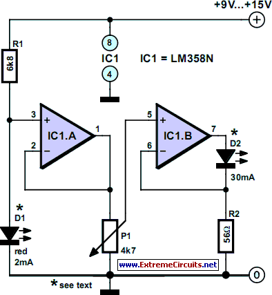
30mA LED Dimmer
If you have ever attempted to dim an LED using a simple potentiometer, it is recognized that this method is not very effective. Similar to standard diodes, the voltage-current characteristic of LEDs is non-linear. Consequently, depending on the potentiometer setting,...

Flashing LED unit
The circuit presented is designed as an LED flasher that creates a rotating effect when the LEDs are arranged appropriately. It operates with very low current consumption and can function using 3V button cells. The first integrated circuit (IC1), a...