


Pseudorandom-sequencer
#pseudorandom
#sequencer
#solid-state relay
#lamp
#flicker
#candle effect
#fireplace simulation
#campfire simulation

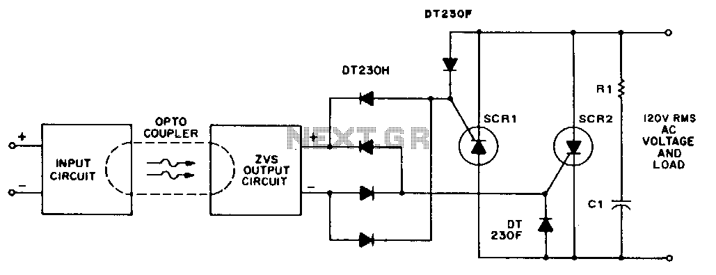
Description: This pseudorandom sequencer operates a solid-state relay. When a low-wattage lamp is powered through the relay, it creates a flickering effect reminiscent of a candle's flame in the wind. Utilizing higher-wattage lamps can simulate the glow of a fireplace or campfire. The effect can be amplified by employing three or more circuits to control multiple lamps. The circuit consists of an oscillator IC1 and a 15-stage pseudorandom sequencer, IC2 through IC4. The sequencer generates a serial bit stream that repeats every 32,767 bits. Feedback from stages 14 and 15 of the sequencer passes through IC4D and returns to the serial input of IC2. An RC network connected to IC4C provides a positive pulse to the sequencer, preventing it from becoming stuck in a zero state at power-up. The remaining XOR gates, IC4A and IC4B, further randomize the output pattern. The serial output from IC4B drives a solid-state relay capable of zero-voltage switching, handling loads up to 1 A at 12 to 280 Vac.
The circuit design utilizes an oscillator (IC1) to generate a clock signal that drives the pseudorandom sequencer composed of multiple integrated circuits (IC2, IC3, IC4). This sequencer is essential for producing a unique bitstream that simulates the flickering effect. The 15-stage sequencer is designed to ensure that the output pattern is sufficiently complex, repeating only after a long sequence of 32,767 bits, which contributes to the realistic flickering effect.
The feedback mechanism involving stages 14 and 15 of the sequencer (via IC4D) is crucial for maintaining the integrity of the output pattern. This feedback loop ensures that the sequencer does not remain in a static state, which could lead to a uniform output rather than the desired randomness. The inclusion of an RC network connected to IC4C serves to initialize the sequencer upon power-up, providing a necessary pulse that guarantees the sequencer starts functioning correctly rather than being stuck in a low-output state.
The XOR gates (IC4A and IC4B) serve to further enhance the randomness of the output signal. By mixing the bits from the sequencer stages, these gates help to create a more complex and less predictable output, which is essential for achieving the desired visual effect when controlling the solid-state relay.
The solid-state relay, driven by the output from IC4B, is a key component in this circuit. Its ability to perform zero-voltage switching allows it to control AC loads without generating electrical noise or transients, making it ideal for applications where flickering lamps are used. This relay can handle loads up to 1 A across a wide voltage range of 12 to 280 Vac, providing versatility for various lighting applications. By leveraging multiple circuits, users can create an array of flickering lamps, enhancing the visual ambiance for settings such as home theaters, fireplaces, or outdoor gatherings.This pseudorandom sequencer drives a solid-state relay. If you power a low-wattage lamp from the relay, the lamp will appear to flicker like a candle"s flame in the wind; using higher-wattage lamps allows you to simulate the blaze of a fireplace or campfire. You can enhance the effect by using three or more such circuits to power an array of lamps. The circuit is comprised of an oscillator IC1 and a 15-stage, pseudorandom sequencer, IC2 through IC4. The sequencer produces a serial bit stream that repeats only every 32, 767 bits. Feedback from the sequencer"s stages 14 and 15 go through IC4D and back to the serial input of IC2. Note the rc network feeding IC4C; the network feeds a positive pulse into the sequencer to ensure that it won"t get stuck with all zeros at power-up.
The leftover XOR gates IC4A and IC4B further scramble the pattern. The serial stream from IC4B drives a solid-state relay that features zero-voltage switching and can handle loads as high as 1 A at 12 to 280 Vac.
The circuit design utilizes an oscillator (IC1) to generate a clock signal that drives the pseudorandom sequencer composed of multiple integrated circuits (IC2, IC3, IC4). This sequencer is essential for producing a unique bitstream that simulates the flickering effect. The 15-stage sequencer is designed to ensure that the output pattern is sufficiently complex, repeating only after a long sequence of 32,767 bits, which contributes to the realistic flickering effect.
The feedback mechanism involving stages 14 and 15 of the sequencer (via IC4D) is crucial for maintaining the integrity of the output pattern. This feedback loop ensures that the sequencer does not remain in a static state, which could lead to a uniform output rather than the desired randomness. The inclusion of an RC network connected to IC4C serves to initialize the sequencer upon power-up, providing a necessary pulse that guarantees the sequencer starts functioning correctly rather than being stuck in a low-output state.
The XOR gates (IC4A and IC4B) serve to further enhance the randomness of the output signal. By mixing the bits from the sequencer stages, these gates help to create a more complex and less predictable output, which is essential for achieving the desired visual effect when controlling the solid-state relay.
The solid-state relay, driven by the output from IC4B, is a key component in this circuit. Its ability to perform zero-voltage switching allows it to control AC loads without generating electrical noise or transients, making it ideal for applications where flickering lamps are used. This relay can handle loads up to 1 A across a wide voltage range of 12 to 280 Vac, providing versatility for various lighting applications. By leveraging multiple circuits, users can create an array of flickering lamps, enhancing the visual ambiance for settings such as home theaters, fireplaces, or outdoor gatherings.This pseudorandom sequencer drives a solid-state relay. If you power a low-wattage lamp from the relay, the lamp will appear to flicker like a candle"s flame in the wind; using higher-wattage lamps allows you to simulate the blaze of a fireplace or campfire. You can enhance the effect by using three or more such circuits to power an array of lamps. The circuit is comprised of an oscillator IC1 and a 15-stage, pseudorandom sequencer, IC2 through IC4. The sequencer produces a serial bit stream that repeats only every 32, 767 bits. Feedback from the sequencer"s stages 14 and 15 go through IC4D and back to the serial input of IC2. Note the rc network feeding IC4C; the network feeds a positive pulse into the sequencer to ensure that it won"t get stuck with all zeros at power-up.
The leftover XOR gates IC4A and IC4B further scramble the pattern. The serial stream from IC4B drives a solid-state relay that features zero-voltage switching and can handle loads as high as 1 A at 12 to 280 Vac.

sequencer
A sequencer used for music is a device that sequences musical events for predictable playback. For early electronic instruments, these sequencers often take the form of a collection of switches that are cued in series and which trigger some other...
Solid-state-relay
A higher input voltage can be utilized if the diode, varistor, ZVS, and power thyristor settings are at compatible levels. For applications exceeding triac current ratings, antiparallel SCRs may be triggered by the ZVS network.
In electronic circuits, the compatibility of...

Schematic Diagram for Model 350 PAFN
When both S1 and R2 are activated, current flows through each of the lamps connected in parallel to the rheostat. The current flow, and consequently the intensity of illumination, can be regulated by adjusting the effective voltage from the batteries,...

Ac-solid-state-relays
When analog signals serve as the logic control, hysteresis from a Schmitt-trigger input can be utilized to prevent high-wave power output. The circuit functions as follows: at low input voltages, Q1 is biased in the off state. Q2 conducts and...

diy-solid-state-relay.html
The primary advantage of a solid-state relay (SSR) over a traditional electromagnetic relay (EMR) is its reduced wear and tear, which enhances its longevity. The S201S01 model from Clear-Cut serves as an exemplary representation of this technology. The following is...

Lamp remote control circuit
The circuit utilizes a 220V AC voltage input that is processed through a capacitor (C1) for bucking, followed by a rectifier bridge (UR) which acts as a barrier-wave rectifier. A filter capacitor (C2) is used to smooth the output voltage...

Lamp Fader schematic
The sunset lamp comes on at full brightness and then slowly fades out over 1.5 hours time and stays off until power is recycled. More: You can use 12 Volt 25 Watt lamps.
The described sunset lamp operates on a 12...

16 Step Sequencer
This project is classified as intermediate to advanced, and it is not recommended for beginners in synthesizers or electronics. The circuit and some explanations are provided, assuming prior experience in project building, troubleshooting, and electronics. Ownership of electronic equipment such...

Lamp-Switching Circuit Circuit
A normally open pushbutton switch (SI) provides a positive input pulse to pin 4 of U1, activating the integrated circuit (IC). The output from U1 at pin 6 delivers base-drive current to a Darlington pair consisting of Q1 and Q2,...