


Pseudorandom Simulated Flicker Sequencer
#pseudorandom
#sequencer
#solid-state relay
#low-wattage
#lamp
#flicker
#simulation
#lighting control

Description: The pseudorandom sequencer drives a solid-state relay. When a low-wattage lamp is powered from the relay, the lamp will flicker like a candle's flame in the wind. Using higher-wattage lamps allows for the simulation of a fireplace or campfire blaze. The effect can be enhanced by utilizing three or more such circuits to power an array of lamps. The circuit consists of an oscillator (IC1) and a 15-stage pseudorandom sequencer (IC2-4). The sequencer generates a serial bit stream that repeats every 32,767 bits. Feedback from stages 14 and 15 of the sequencer is routed through IC4D back to the serial input of IC2. An RC network feeds IC4C, providing a positive pulse to the sequencer to prevent it from being stuck in a zero state at power-up. The remaining XOR gates (IC4A and IC4B) further scramble the output pattern. The serial stream from IC4B drives a solid-state relay that features zero-voltage switching and can manage loads up to 1 A at 12 to 280 Vac.
The described circuit functions as an innovative lighting control system that utilizes a pseudorandom sequencer to create flickering light effects. The primary components include an oscillator and a sequencer, which work in tandem to generate a unique serial bit stream. This bit stream is characterized by a period of 32,767 bits, ensuring a long cycle before the pattern repeats, thus enhancing the unpredictability of the light output.
The feedback mechanism implemented through stages 14 and 15 allows for dynamic adjustment of the sequencer's operation, ensuring that the output remains varied. The integration of the RC network serves a critical role during the power-up phase, delivering a pulse that prevents the sequencer from entering a non-functional state. This design consideration is vital for reliable operation, particularly in environments where power fluctuations may occur.
The XOR gates (IC4A and IC4B) introduce additional complexity to the output pattern, further enhancing the realism of the simulated flame effects. By scrambling the output, these gates contribute to a more natural flickering effect, making the lighting more visually appealing.
The solid-state relay operates with zero-voltage switching, which minimizes electrical noise and enhances the lifespan of both the relay and the connected lighting elements. Capable of handling loads up to 1 A across a wide voltage range (12 to 280 Vac), this relay is suitable for various applications, from decorative lighting to more significant installations. The use of multiple circuits can create a more extensive lighting array, intensifying the effect and providing a versatile solution for ambient lighting needs. The pseudorandom sequencer drives a solid-state relay. If you power a low-wattage lamp from the re lay, the lamp will appear to flicker like a candle"s flame in the wind; using higher-wattage lamps allows you to simulate the blaze of a fireplace or campfire. You can enhance the effect by using three or more such circuits to power an array of lamps. The circuit comprises an oscillator, IC1, and a 15-stage, pseudorandom sequencer, IC2-4. The sequencer produces a serial bit stream that repeats only every 32 767 bits. Feedback from the sequencer"s stages 14 and 15 go through IC4D and back to the serial input of IC2. Notice the RC network that feeds IC4C; the network feeds a positive pulse into the sequencer to ensure that it won"t get stuck with all zeros at power-up.
The leftover XOR gates IC4A and IC4B further scramble the pattern. The serial stream from IC4B drives a solid-state relay that features zero-voltage switching and can handle loads as high as 1 A at 12 to 280 Vac.
The described circuit functions as an innovative lighting control system that utilizes a pseudorandom sequencer to create flickering light effects. The primary components include an oscillator and a sequencer, which work in tandem to generate a unique serial bit stream. This bit stream is characterized by a period of 32,767 bits, ensuring a long cycle before the pattern repeats, thus enhancing the unpredictability of the light output.
The feedback mechanism implemented through stages 14 and 15 allows for dynamic adjustment of the sequencer's operation, ensuring that the output remains varied. The integration of the RC network serves a critical role during the power-up phase, delivering a pulse that prevents the sequencer from entering a non-functional state. This design consideration is vital for reliable operation, particularly in environments where power fluctuations may occur.
The XOR gates (IC4A and IC4B) introduce additional complexity to the output pattern, further enhancing the realism of the simulated flame effects. By scrambling the output, these gates contribute to a more natural flickering effect, making the lighting more visually appealing.
The solid-state relay operates with zero-voltage switching, which minimizes electrical noise and enhances the lifespan of both the relay and the connected lighting elements. Capable of handling loads up to 1 A across a wide voltage range (12 to 280 Vac), this relay is suitable for various applications, from decorative lighting to more significant installations. The use of multiple circuits can create a more extensive lighting array, intensifying the effect and providing a versatile solution for ambient lighting needs. The pseudorandom sequencer drives a solid-state relay. If you power a low-wattage lamp from the re lay, the lamp will appear to flicker like a candle"s flame in the wind; using higher-wattage lamps allows you to simulate the blaze of a fireplace or campfire. You can enhance the effect by using three or more such circuits to power an array of lamps. The circuit comprises an oscillator, IC1, and a 15-stage, pseudorandom sequencer, IC2-4. The sequencer produces a serial bit stream that repeats only every 32 767 bits. Feedback from the sequencer"s stages 14 and 15 go through IC4D and back to the serial input of IC2. Notice the RC network that feeds IC4C; the network feeds a positive pulse into the sequencer to ensure that it won"t get stuck with all zeros at power-up.
The leftover XOR gates IC4A and IC4B further scramble the pattern. The serial stream from IC4B drives a solid-state relay that features zero-voltage switching and can handle loads as high as 1 A at 12 to 280 Vac.

Ac-solid-state-relays
When analog signals serve as the logic control, hysteresis from a Schmitt-trigger input can be utilized to prevent high-wave power output. The circuit functions as follows: at low input voltages, Q1 is biased in the off state. Q2 conducts and...

16 step sequencer schematic
After extensive searching online, a 16-step sequencer schematic was not found that did not require an Arduino, PIC, or another digital controller. A simple 3-chip analog 16-step sequencer with variable speed and arpeggio has been developed, drawing from various inspirations...

High-rise residential walkway lighting control circuit
Pressing the button switch Sl-Sn activates the circuit, turning on the transformer T. The low-voltage alternating current from the secondary winding is directed to a bridge rectifier and a filter capacitor Ci, which produces a DC voltage. This voltage energizes...
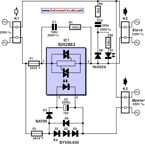
Master/Slave Switch
The circuit detects the mains current supplied to a master device and controls the on/off state of slave equipment. This functionality is particularly beneficial in environments such as hi-fi systems or home computers, where multiple peripheral devices can be managed...

Lamp remote control circuit
The circuit utilizes a 220V AC voltage input that is processed through a capacitor (C1) for bucking, followed by a rectifier bridge (UR) which acts as a barrier-wave rectifier. A filter capacitor (C2) is used to smooth the output voltage...

Lamp Fader schematic
The sunset lamp comes on at full brightness and then slowly fades out over 1.5 hours time and stays off until power is recycled. More: You can use 12 Volt 25 Watt lamps.
The described sunset lamp operates on a 12...

The PCS Scenemaster
The PCS SceneMaster Model LM4LS2 was awarded "Best Web Site" by Home Automator Magazine and was installed in the spring of 1999. This controller can ramp lights on and off and create "scenes," where a single X-10 command can generate...

gate sequencer
The CGS89 is a sequencer designed to deliver pulsed or gated events for rhythm and percussion, trigger other sequencers, or select stages in Programmers like the Serge R15 PRG. It serves as a replacement for the first-generation Serge R10 SEQ...

sunrise lamp
This circuit gradually illuminates a 120VAC lamp over an approximate 20-minute period. A bridge rectifier provides 120V DC to the MOSFET and the 60-watt lamp. A 6.2K, 5-watt resistor along with a Zener diode is utilized to reduce the voltage...