


Rear Light After Glow (For Bicycles)

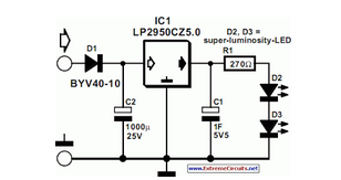
Description: This article is relevant only to readers whose bicycle lights are powered by a dynamo. The regulations regarding bicycle lights in the United Kingdom are stricter than in other countries, making the use of a dynamo uncommon in this region. From a traffic safety perspective, it is advisable (and in the UK, mandatory) for cyclists to have their rear lamp illuminated even when stationary. Modifying the existing rear light to include an afterglow feature is not particularly complex; it simply requires a sufficiently large energy reservoir. Since the afterglow is needed only for short intervals, a battery is unnecessary; a capacitor with a large capacitance, such as 1 F, is adequate. The circuit diagram illustrates that the standard rear light bulb is replaced with two series-connected bright LEDs, D2 and D3, which are clearly visible with a current of only 6 mA (in contrast to the 50 mA required by the bulb). The current is regulated by series resistor R1. The LEDs are connected in parallel with the 1 F capacitor, C1. Given that the working voltage of this capacitor is only 5.5 V, it remains physically compact despite its high capacitance. An effective voltage regulator is necessary to adequately limit the dynamo voltage. Standard regulators are unsuitable for this application as they do not function at low voltages and would discharge the capacitor when the bicycle is stationary. Fortunately, a low-dropout regulator, the Type LP2950CZ5.0, fulfills the requirements effectively. The dynamo output voltage must be rectified before being fed into the regulator. In this circuit, this is achieved using half-wave rectifier D1 and buffer capacitor C2. Diode D1 is a Schottky type to minimize losses, which is crucial for this application, as grounding through the bicycle frame can introduce additional losses. The buffer capacitor's value has been selected to exceed the minimum requirements, ensuring that C1 is charged during the negative half-cycles of the dynamo voltage.
The circuit described integrates several components to create an efficient lighting system for bicycles powered by a dynamo. The use of two series-connected bright LEDs (D2 and D3) as replacements for the traditional rear light bulb not only reduces power consumption but also enhances visibility. The series resistor (R1) is critical for limiting the current flowing through the LEDs, ensuring that they operate within safe parameters while providing adequate brightness.
The 1 F capacitor (C1) serves as the energy reservoir, allowing for a brief afterglow when the bicycle is stationary. This capacitor is charged during the operation of the dynamo, which generates alternating current (AC) that is rectified by the Schottky diode (D1). The choice of a Schottky diode is significant due to its low forward voltage drop, which helps to minimize power losses, thus maximizing the efficiency of the system.
The LP2950CZ5.0 low-dropout voltage regulator is employed to maintain a stable output voltage, ensuring that the LEDs receive constant power regardless of fluctuations in the dynamo output. This regulator is particularly suited for applications requiring low input-output voltage differentials, making it ideal for use with the low voltage generated by the dynamo.
In summary, this circuit design effectively addresses the need for a reliable and energy-efficient rear light system for bicycles powered by a dynamo, adhering to UK regulations while enhancing safety for cyclists. The integration of modern components such as LEDs and low-dropout regulators reflects an advancement in bicycle lighting technology, promoting both functionality and energy efficiency.This article is of interest only to readers whose bicycle lights are powered by a dynamo. The laws on bicycle lights in the United Kingdom are stricter than in other countries and a dynamo is, therefore, a rarity in this country. From the point of view of traffic safety it is advisable (in UK obligatory) for cyclists to have the rear lamp of their
bicycle to light even when they are at standstill. In principle, it is not very difficult to modify the existing rear light with afterglow: all this needs is a large enough energy reservoir. Since the after-glow is required for short periods of time only, a battery is not required: a large value capacitor, say, 1 F, is quite sufficient.
As the diagram shows, in the present circuit, the normal rear light bulb is replaced by two series-connected bright LEDs, D2 and D3. These are clearly visible with a current of only 6 mA (compared with 50 mA of the bulb). The current is set with series resistor R1. The LEDs are shunted by the 1 F capacitor, C1. Since the working voltage of this component is only 5. 5 V, it is, in spite of its high value, physically small. An effective regulator is needed to limit the dynamo voltage adequately. Normal regulators cannot be used here, since they do not work at low voltages. Moreover, such a device would discharge the capacitor when the cycle is at standstill. Fortunately, there is a low-drop type that meets the present requirements nicely: the Type LP2950CZ5.
0. Of course, the dynamo output voltage needs to be rectified before it can be applied to the regulator. In the present circuit, this is effected by half-wave rectifier D1 and buffer capacitor C2. Diode D1 is a Schottky type to keep any losses low important for this application, because the ground connection via the bicycle frame usually causes some losses as well.
The value of buffer capacitor has been chosen well above requirements to ensure that C1 is charged during the negative half cycles of the dynamo voltage.
The circuit described integrates several components to create an efficient lighting system for bicycles powered by a dynamo. The use of two series-connected bright LEDs (D2 and D3) as replacements for the traditional rear light bulb not only reduces power consumption but also enhances visibility. The series resistor (R1) is critical for limiting the current flowing through the LEDs, ensuring that they operate within safe parameters while providing adequate brightness.
The 1 F capacitor (C1) serves as the energy reservoir, allowing for a brief afterglow when the bicycle is stationary. This capacitor is charged during the operation of the dynamo, which generates alternating current (AC) that is rectified by the Schottky diode (D1). The choice of a Schottky diode is significant due to its low forward voltage drop, which helps to minimize power losses, thus maximizing the efficiency of the system.
The LP2950CZ5.0 low-dropout voltage regulator is employed to maintain a stable output voltage, ensuring that the LEDs receive constant power regardless of fluctuations in the dynamo output. This regulator is particularly suited for applications requiring low input-output voltage differentials, making it ideal for use with the low voltage generated by the dynamo.
In summary, this circuit design effectively addresses the need for a reliable and energy-efficient rear light system for bicycles powered by a dynamo, adhering to UK regulations while enhancing safety for cyclists. The integration of modern components such as LEDs and low-dropout regulators reflects an advancement in bicycle lighting technology, promoting both functionality and energy efficiency.This article is of interest only to readers whose bicycle lights are powered by a dynamo. The laws on bicycle lights in the United Kingdom are stricter than in other countries and a dynamo is, therefore, a rarity in this country. From the point of view of traffic safety it is advisable (in UK obligatory) for cyclists to have the rear lamp of their
bicycle to light even when they are at standstill. In principle, it is not very difficult to modify the existing rear light with afterglow: all this needs is a large enough energy reservoir. Since the after-glow is required for short periods of time only, a battery is not required: a large value capacitor, say, 1 F, is quite sufficient.
As the diagram shows, in the present circuit, the normal rear light bulb is replaced by two series-connected bright LEDs, D2 and D3. These are clearly visible with a current of only 6 mA (compared with 50 mA of the bulb). The current is set with series resistor R1. The LEDs are shunted by the 1 F capacitor, C1. Since the working voltage of this component is only 5. 5 V, it is, in spite of its high value, physically small. An effective regulator is needed to limit the dynamo voltage adequately. Normal regulators cannot be used here, since they do not work at low voltages. Moreover, such a device would discharge the capacitor when the cycle is at standstill. Fortunately, there is a low-drop type that meets the present requirements nicely: the Type LP2950CZ5.
0. Of course, the dynamo output voltage needs to be rectified before it can be applied to the regulator. In the present circuit, this is effected by half-wave rectifier D1 and buffer capacitor C2. Diode D1 is a Schottky type to keep any losses low important for this application, because the ground connection via the bicycle frame usually causes some losses as well.
The value of buffer capacitor has been chosen well above requirements to ensure that C1 is charged during the negative half cycles of the dynamo voltage.

Dynamo Current and Voltage Regulator
In the typical dynamo charging circuit, B+ and B- are the battery connections. D+ and D- go to the dynamo brushes, while DF is the field connection, with its other end returned to D+ inside the dynamo. Please note that...

Bicycle Sensing
Bicycle sensors serve two primary functions: recording the motion of the bicycle for collision reconstruction and transmitting signals to the bicycle controls to ensure proper navigation. This necessitates several component specifications, as the sensors need to be robust enough to...
Rear Light After Glow (For Bicycles)
This article is relevant only to readers whose bicycle lights are powered by a dynamo. The regulations regarding bicycle lights in the United Kingdom are more stringent.
Dynamo-powered bicycle lights are an essential component for cyclists, providing illumination without the need...

Bicycle Rear-Light Afterglow Circuit
This article is relevant only to readers whose bicycle lights are powered by a dynamo. The regulations regarding bicycle lights in the United Kingdom are stricter than in many other countries, making dynamos a rarity in the UK. For safety...

Bicycle Speedometer With Hub Dynamo
The concept for this circuit was developed due to issues experienced with a bicycle's wireless speedometer. This device comprises two components: the cycle computer and a transmitter mounted on the front fork. A small magnet is affixed to the spokes,...

Simple Safety Circuit Circuit
The simple two-hand safety control switch consists of two pushbutton switches connected in series; both must be depressed to energize the relay.
The two-hand safety control switch is designed to enhance safety in applications where the operation of machinery or equipment...

Do not drink and drive I wish you a safe journey home Language Integrated Circuits
Do not drink and drive. Wishing you a safe journey home. Language Integrated Circuits.
Language Integrated Circuits (LICs) are specialized electronic components designed to facilitate the processing of language-based data within various applications. These circuits integrate multiple functions, such as signal...
bicycle speed indicator circuit explained
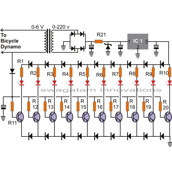
The article presents a circuit that can be used for indicating the riding speed of a bicycle. The bicycle speedometer circuit explained here utilizes standard components such as transistors and LEDs to effectively display a clear 10-step, accurately calibrated linear...

Bicycle speed circuit
Cycling is a common mode of transportation. When paired with a bicycle speedometer, cyclists can effectively monitor their speed, which is particularly beneficial for training purposes. The bicycle speedometer circuit, as illustrated in Figure 5-33, utilizes the relationship between the...