


solid state tube light choke
#tube light
#solid state
#capacitors
#diodes
#electronic choke
#energy efficient
#low voltage
#100 watt
#lighting solution
#circuit design
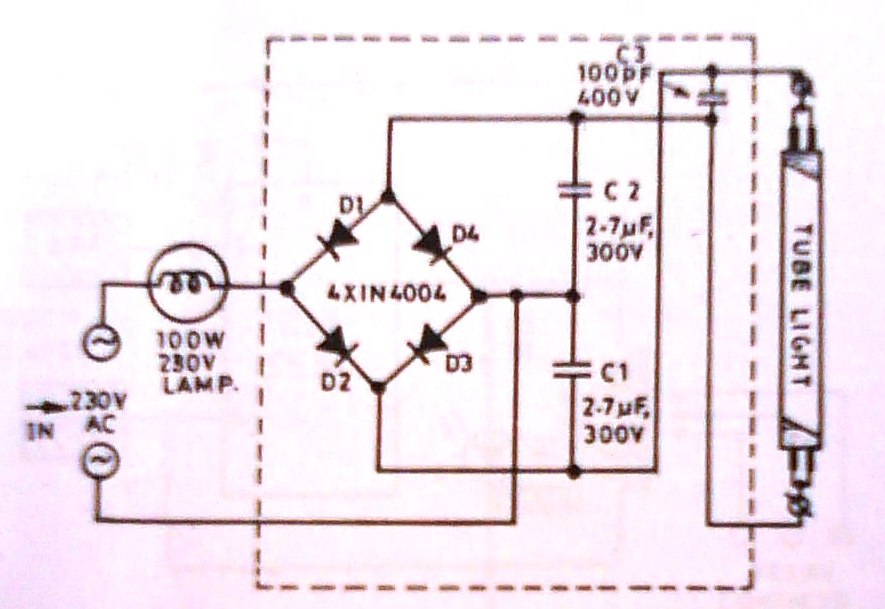
Description: The advantages of tube lights over filament bulbs are well known. However, tube lights also have their drawbacks. They do not operate effectively at lower voltages, are relatively expensive, and have a tendency to burn out easily. This document presents a unique solid-state electronic design. The circuit, illustrated in the schematic, employs two capacitors and four diodes and is designed to work with a 100-watt bulb. Tube lights operated with this choke were found to function at voltages as low as 120 volts (within 220-volt lines). The circuit supplies pulsating voltage to the fluorescent tube light mounted on a conventional stand.
This solid-state electronic design addresses the limitations of traditional tube lights by enabling their operation at lower voltages, significantly enhancing their versatility and usability in various applications. The circuit's configuration, which includes two capacitors and four diodes, plays a crucial role in converting the input AC voltage into a suitable form for the fluorescent tube light.
The use of capacitors in the circuit serves multiple purposes. They not only filter and smooth the pulsating voltage output but also provide energy storage, which helps maintain a steady supply of power to the tube light. The diodes, arranged in a bridge rectifier configuration, facilitate the conversion of AC voltage to a pulsating DC voltage, which is necessary for the operation of the fluorescent tube light. This design is particularly advantageous as it allows the tube light to operate efficiently even at lower voltage levels, which are commonly found in residential and commercial electrical systems.
The incorporation of a choke further enhances the performance of the circuit by regulating the current flowing through the tube light. This regulation is vital for preventing flickering and ensuring stable illumination. The ability to operate at voltages as low as 120 volts makes this design suitable for environments where voltage fluctuations are common, thereby increasing the reliability and lifespan of the tube lights.
Overall, this innovative design not only improves the operational efficiency of tube lights but also addresses common issues associated with traditional lighting solutions, making it a valuable advancement in the field of electronic lighting systems.The advantages of tube light over filament bulbs are well known. But these tube lights have problems too. They refuse to work at lower voltages, they are costly, burn out easily and so on. So, presented here is a unique solid state electronic design. The circuit is shown in schematic a it uses two capacitors and four diodes and work along with a 100 wat t bulb. The tube lights operated with this choke were found to work at voltage as low as 120 volts(in the 220 volt lines). The circuit provides a pulsating voltages to the fluorescent tube light fixed on a conventional stand.
This solid-state electronic design addresses the limitations of traditional tube lights by enabling their operation at lower voltages, significantly enhancing their versatility and usability in various applications. The circuit's configuration, which includes two capacitors and four diodes, plays a crucial role in converting the input AC voltage into a suitable form for the fluorescent tube light.
The use of capacitors in the circuit serves multiple purposes. They not only filter and smooth the pulsating voltage output but also provide energy storage, which helps maintain a steady supply of power to the tube light. The diodes, arranged in a bridge rectifier configuration, facilitate the conversion of AC voltage to a pulsating DC voltage, which is necessary for the operation of the fluorescent tube light. This design is particularly advantageous as it allows the tube light to operate efficiently even at lower voltage levels, which are commonly found in residential and commercial electrical systems.
The incorporation of a choke further enhances the performance of the circuit by regulating the current flowing through the tube light. This regulation is vital for preventing flickering and ensuring stable illumination. The ability to operate at voltages as low as 120 volts makes this design suitable for environments where voltage fluctuations are common, thereby increasing the reliability and lifespan of the tube lights.
Overall, this innovative design not only improves the operational efficiency of tube lights but also addresses common issues associated with traditional lighting solutions, making it a valuable advancement in the field of electronic lighting systems.The advantages of tube light over filament bulbs are well known. But these tube lights have problems too. They refuse to work at lower voltages, they are costly, burn out easily and so on. So, presented here is a unique solid state electronic design. The circuit is shown in schematic a it uses two capacitors and four diodes and work along with a 100 wat t bulb. The tube lights operated with this choke were found to work at voltage as low as 120 volts(in the 220 volt lines). The circuit provides a pulsating voltages to the fluorescent tube light fixed on a conventional stand.
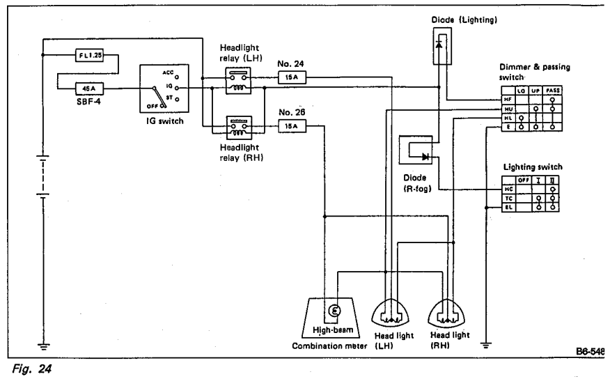
Whats the purpose of the diodes in this circuit
Understanding the headlight wiring in a car involves examining the purpose of two diodes in the circuit diagram. The circuit allows for two independent methods of activating the light relays: through the light switch or by flashing the high beams....

Low voltage lamp flasher
The circuit consists of a relaxation oscillator created by Q1 and an SCR flip-flop formed by Q2 and Q3. When the supply voltage is applied to the circuit, the timing capacitor C1 charges to the firing point of the Programmable...

Low voltage flasher
Applying voltage to the circuit triggers SCR1. With SCR1 on, the voltage on the anode of SCR2 rises until SCR2 triggers to commutate SCR1. The voltage on the gate of SCR1 will swing negative at this time, and only after...

Solid state winch control
Interest is expressed in constructing a solid-state control system for a Warn 8274 self-recovery winch. The existing control method employs four constant-duty 200 amp solenoids. Two are switched in parallel to connect the field 1 terminal on the motor to...

Low voltage detector
The values of R1, R2, and D1 are selected based on the voltage applied. Using a 12-volt battery, R1 is set to 10 kΩ, R2 to 5 kΩ, and D1 is a 5-volt zener diode or a string of forward-biased...

Low voltage regulators
These short-circuit protected regulators provide output voltages of 6, 7, and 9 V from a nominal automobile battery supply of 13 V. They are also compatible with smoothed DC outputs from transformer/rectifier circuits. Two configurations are designed for both positive...

The battery voltage is low frequency amplifying circuit diagram 1v
The battery voltage is 1V for a low-frequency amplifying circuit, which can operate with a power supply voltage ranging from 1V to 1.7V, making it suitable for use with small batteries. The circuit provides an output power of 80mW with...

case stepper
Beige Bag Software has been offering affordable and innovative circuit design tools since 1990. B2 Spice provides schematics as well as analog, digital, and mixed-mode electronic circuit simulation. It integrates with EAGLE and CADSTAR PCB software.
B2 Spice is a powerful...
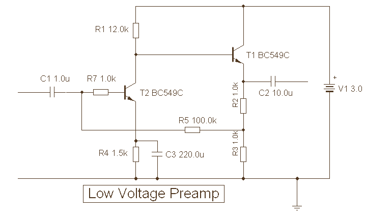
Low Voltage Preamplifier
The provided description pertains to a unique low voltage variant of an audio preamp. The emitter voltage of T1 is biased close to half the supply voltage, which is 1.5V. This biasing allows for the maximum output voltage swing. The...