


Stair case wiring circuit diagram OR How to control a lamp from two different places by two 2-way switches
#2-way switch
#lamp control
#staircase wiring
#electrical wiring
#home automation
#light switch
#circuit diagram
#electrical circuit
#home lighting
#DIY electronics
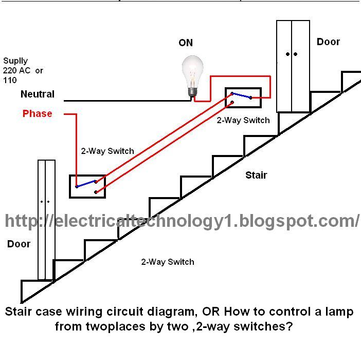
Description: The circuit is complete, and the bulb is ON. To turn OFF the bulb from the upper switch at the top of the stairs, simply turn OFF the switch, which will break the circuit and turn the bulb OFF. The bulb can be turned ON again by activating the same switch. In other words, the bulb can be controlled from the upper switch at the top of the stairs. Similarly, the same control can be achieved from the lower switch at the bottom of the stairs. Returning to the circuit in the picture, when the circuit is complete, the bulb remains ON. To turn OFF the bulb from the lower switch, simply turn OFF the switch, breaking the circuit and turning the bulb OFF. The bulb can be turned ON again by activating this switch. This is a staircase circuit diagram that allows control of a bulb from two different locations. The bulb can be switched OFF and ON from both switches simultaneously, enabling control from both the upper and lower switches.
The staircase circuit, commonly referred to as a two-way switching circuit, utilizes two switches to control a single load, such as a light bulb, from two different locations. This configuration is particularly useful in staircases or long hallways where accessibility to a switch from both ends is desired.
In the typical wiring setup, the two switches are connected in a way that allows them to control the same light fixture. Each switch has three terminals: one common terminal and two traveler terminals. The common terminal connects to the power source or the load (the bulb), while the traveler terminals connect to the corresponding traveler terminals of the other switch.
When the first switch is toggled, it either connects or disconnects the circuit, allowing current to flow to the bulb or interrupting it. The second switch can then be used to reverse the state of the bulb, effectively allowing the user to turn the light ON or OFF regardless of the position of the other switch. This creates a versatile control system that enhances convenience and safety in areas where lighting is essential.
In summary, this two-way switching circuit enables efficient control of lighting from multiple locations, ensuring that the user can operate the light fixture from both the upper and lower positions of the staircase. The design promotes ease of use and flexibility in lighting control, making it an essential feature in modern electrical installations.You can see that circuit is complete and bulb is ON. Suppose you want to OFF bulb from the upper switch at top of stair, simply Switch OFF the switch then circuit will break and the bulb will be OFF. You can switch ON the bulb again to switch ON this Switch. In other words you can OFF and ON bulb from upper switch at the top of stair. Obviously; you can do same from the upper and bottom switch, so let`s see how we can do that from that switch at the bottom of stair. Now return to circuit again in the pic, In this case you can see that circuit is complete and bulb is ON.
Suppose you want to OFF the bulb from the lower switch at bottom of stair. Simply OFF the switch, then again circuit will break and the bulb will be OFF. You can switch ON the bulb again to switch ON this Switch This is a stair case circuit diagram by which we can control a bulb from two different places. We can switch OFF and Switch ON the bulb from both switches at the same time. in other words we can control (OFF or ON) the bulb from upper and lower switches.
The staircase circuit, commonly referred to as a two-way switching circuit, utilizes two switches to control a single load, such as a light bulb, from two different locations. This configuration is particularly useful in staircases or long hallways where accessibility to a switch from both ends is desired.
In the typical wiring setup, the two switches are connected in a way that allows them to control the same light fixture. Each switch has three terminals: one common terminal and two traveler terminals. The common terminal connects to the power source or the load (the bulb), while the traveler terminals connect to the corresponding traveler terminals of the other switch.
When the first switch is toggled, it either connects or disconnects the circuit, allowing current to flow to the bulb or interrupting it. The second switch can then be used to reverse the state of the bulb, effectively allowing the user to turn the light ON or OFF regardless of the position of the other switch. This creates a versatile control system that enhances convenience and safety in areas where lighting is essential.
In summary, this two-way switching circuit enables efficient control of lighting from multiple locations, ensuring that the user can operate the light fixture from both the upper and lower positions of the staircase. The design promotes ease of use and flexibility in lighting control, making it an essential feature in modern electrical installations.You can see that circuit is complete and bulb is ON. Suppose you want to OFF bulb from the upper switch at top of stair, simply Switch OFF the switch then circuit will break and the bulb will be OFF. You can switch ON the bulb again to switch ON this Switch. In other words you can OFF and ON bulb from upper switch at the top of stair. Obviously; you can do same from the upper and bottom switch, so let`s see how we can do that from that switch at the bottom of stair. Now return to circuit again in the pic, In this case you can see that circuit is complete and bulb is ON.
Suppose you want to OFF the bulb from the lower switch at bottom of stair. Simply OFF the switch, then again circuit will break and the bulb will be OFF. You can switch ON the bulb again to switch ON this Switch This is a stair case circuit diagram by which we can control a bulb from two different places. We can switch OFF and Switch ON the bulb from both switches at the same time. in other words we can control (OFF or ON) the bulb from upper and lower switches.
home automation Installation
First and foremost, if one is not skilled with tools and electrical systems, it is advisable to hire a qualified electrician rather than attempting to undertake this task independently. The electrician should review this page for specific cautions and advice....

Light Switch
Light Switch. This is a light switch or light-activated relay circuit. The relay activates when the light-dependent resistor (LDR) is uncovered and deactivates when the LDR is covered. It is adjustable for sensitivity and includes an LED indicator.
This light-activated relay...

Home Electrical Wiring
When considering a backup power system, adding an electric circuit, or installing a new appliance, it is crucial to understand the basics of home electrical wiring and the applicable codes. First, it is important to review how electricity reaches a...

Computerize Your Room/House
You have read about computerized rooms or seen home automation products advertised in electronics magazines. You have decided to try it yourself. However, it is important to note that this project is not inexpensive. A computer is required, which is...

Single multi-lamp switch control circuit 2
Figure 296 illustrates a control circuit that utilizes a switch (S) to manage three lamps (E1, E2, and E3) in a lighting system, suitable for controlling a chandelier in a living room. When the switch is off, all lights are...

Quartz Controlled Bedroom Light Switch
This is a simple automatic light switch circuit designed for bedrooms. After construction, connect the input terminals of this circuit in parallel to the internal buzzer terminals of a quartz alarm clock. When the clock alarm is activated, the circuit...

Installing Bathroom Electrical Wiring
The following circuit illustrates the installation of a bathroom electrical wiring circuit diagram. Features include safety, energy savings, and enhancement of home functionality.
This circuit diagram provides a comprehensive overview of the electrical wiring necessary for a bathroom installation. It typically...

Door Light Switch
This automatic door light switch circuit activates a lamp when a door is opened and deactivates it when the door is closed again. The working principle of the circuit involves a sensor that detects the door's position.
The automatic door light...