


Strobo triggering schematics
#stroboscope
#trigger circuit
#triac
#external trigger
#pulse trigger
#light control
#10V pulse
#professional stroboscope
#trigger switch


Description: This page contains some information on circuits which can be used for triggering stroboscopes from external circuits. The circuits here are designed to be integrated into stroboscope circuits so that they can be triggered using an external trigger pulse. The standard trigger pulse used in professional stroboscope controllers is a 3-10V pulse. If you don't already have a suitable controller, you can build one based on my stroboscope controller design. This circuit takes a 10V trigger pulse to trigger a TRIAC which connects the points A and B together. This circuit can be placed in almost any stroboscope circuit in place of the trigger switch or the trigger TRIAC. Stroboscope circuits use lethal voltages, so you must be very careful when operating with them. When the stroboscopes are triggered using an external signal, there are some extra safety considerations. The safest way is to provide complete galvanic isolation of a few kV between the trigger input and the stroboscope circuitry. This isolation can be achieved using an optoisolator or transformer isolation. The circuit works in the following way:
The +10V trigger pulse enters the MOC3023 optoisolator. The output of the optoisolator starts to conduct because of the current that flows through the optoisolator output and NEON bulb. When the TRIAC starts to conduct, the triggering of the stroboscope happens. At the same time when the TRIAC conducts, the current in the circuit formed by the NEON bulb and MOC3023 stops flowing. When the triggering capacitor is discharged, the TRIAC itself stops conducting. Using this circuit, a short pulse applied to the input of MOC3023 will trigger the stroboscope once. If the input of MOC3023 is kept constantly at +10V, the stroboscope keeps triggering constantly at its maximum rate because the circuit retriggers every time the voltage across the TRIAC exceeds around 90V. The isolation between the trigger signal and the stroboscope circuit is provided by the MOC3023 optoisolator, which can withstand pulses up to 7500V. This isolation level is more than adequate in typical applications. To fully enjoy this level of high voltage isolation, it is essential to maintain sufficient clearance on the circuit board between the input and output pins of the MOC3023 optoisolator.
When connecting the output connectors of the module to the stroboscope circuit (in the same way as described above), the triggering of the circuit works by simply feeding a trigger pulse to the isolated signal input of the module. Standard 3-10V trigger pulses work effectively with the module when a 470-ohm resistor is placed in series with the module input. This circuit performs well with the resistor alone but may be slightly sensitive to noise in the trigger cable, causing it to flash in noisy environments with other light controllers present. To mitigate this issue, a 333 nF capacitor can be added to filter out small noise spikes, preventing accidental triggering of the stroboscope. Real trigger pulses from the controller will still trigger the circuit without issues.
Another option for providing isolation between the trigger signal and the stroboscope is to use transformer isolation. In this approach, the trigger pulse is fed to the gate of the TRIAC or thyristor through a transformer. Various types of transformers can be utilized, but the optimal choice would be a pulse transformer designed for triggering TRIACs, which provides the necessary isolation levels (at least a few kV). Caution is advised, as the high voltage of stroboscopes can cause severe and potentially fatal shocks. The energy storage capacitor can retain dangerously high voltage even after the power is removed from the board.This page contains some information on circuits which can be used for triggering stroboscopes from external circuits. The circuit here are designed to be integrate to strboscope circuits so that they can triggered using external trigger pulse.
The standard trigger pulse used in professional stroboscope controllers is 3-10V pulse. If you don't already have a suitable controller, you can built one based on my stroboscope controller design. This circuit takes 10V trigger pulse to trigger a triac which connect the points A and B together. This circuit can be placed to almost any stroboscope circuit in place of the trigger switch or the trigger triac.
Stroboscope circuit use lethal voltages, so you must be very careful when operating with them. When the stroboscopes are triggered using an external signal, then there are some extra safety things to consider. The safest way is to provide a complete galvanic isolation of few kV between the trigger input and the stroboscope circuitry.
This isolation can be done using and optoisolator or transformer isolation. The circuit works in the following way: The +10V trigger pulse enters MOC3023 optoisolator The output of the optoisolator starts to conduct because of the current which starts to flow though optoisolator output and NEON bulb When the TRIAC starts to condict the triggering of the stroboscope happens At the same time when the TRIAC conducts, the current on the circuit formaed by NEON bulb and MOC3023 stops to flow When the triggering capacitor is discharged the TRIAC itself stops to condict Using this circuit a short pulse applied to the input of MOC3023 will trigger the stroboscope one. If the input of MOC3023 is kept constantly at +10V, the stroboscope keeps triggering constantly at it's maximum rate, because the circuit retriggers every time when the voltage over TRIAC exceeds around 90V.
The isolation between the trigger signal and the stroboscope circuit is provided by MOC3023 optoisolator, which can withstand pulsed up to 7500V. This isolation level is more than dequate in typical applications. If you want really anjoy this kind of high voltage isolation you must keep in mind to keep enough clearance in the circuit board between the input and output pins of the MOC3023 optoisolator.
When you connect the output connectors of the module to the stroboscope circuit (same way as the circuits descrbed above) you get it work there. The triggering of the circuit works by just feeding a trigger pulse to the isolated signal input of the module.
I have foudn out that standard 3-10V trigger pulses work nicely with the module when you put a 470 ohm resistor in series with the module input and feed the trigger pulse to this system. This circuit worked quite well with the resitor only, was a little but to sensitive to the noise in the trigger cable (flashed on noisy enviroments where there are other light controllers around by itself randomly).
To help this problem I added the 333 nF capacitor to filter out very small noise spikes to not to trugger the stroboscope. The real trigger pulses from controller will still trigger the circuit without any problems. Another option to provide the isolation between trigger signal and the stroboscope is to use transformer isolation.
In this approach the trigger pulse is fed to the gate of the TRIAC or thyristor though a transformer. There are amny types of transformers which can be used, but the best selection for those would be a pulse transformer which is designed for triggering triacs and provides the necessary isolation levels (at least few kV).
CAUTION - high voltage of strobes can cause a nasty and possibly fatal shock. The energy storage capacitor can retain dangerous high voltage after power is removed from the board.
The +10V trigger pulse enters the MOC3023 optoisolator. The output of the optoisolator starts to conduct because of the current that flows through the optoisolator output and NEON bulb. When the TRIAC starts to conduct, the triggering of the stroboscope happens. At the same time when the TRIAC conducts, the current in the circuit formed by the NEON bulb and MOC3023 stops flowing. When the triggering capacitor is discharged, the TRIAC itself stops conducting. Using this circuit, a short pulse applied to the input of MOC3023 will trigger the stroboscope once. If the input of MOC3023 is kept constantly at +10V, the stroboscope keeps triggering constantly at its maximum rate because the circuit retriggers every time the voltage across the TRIAC exceeds around 90V. The isolation between the trigger signal and the stroboscope circuit is provided by the MOC3023 optoisolator, which can withstand pulses up to 7500V. This isolation level is more than adequate in typical applications. To fully enjoy this level of high voltage isolation, it is essential to maintain sufficient clearance on the circuit board between the input and output pins of the MOC3023 optoisolator.
When connecting the output connectors of the module to the stroboscope circuit (in the same way as described above), the triggering of the circuit works by simply feeding a trigger pulse to the isolated signal input of the module. Standard 3-10V trigger pulses work effectively with the module when a 470-ohm resistor is placed in series with the module input. This circuit performs well with the resistor alone but may be slightly sensitive to noise in the trigger cable, causing it to flash in noisy environments with other light controllers present. To mitigate this issue, a 333 nF capacitor can be added to filter out small noise spikes, preventing accidental triggering of the stroboscope. Real trigger pulses from the controller will still trigger the circuit without issues.
Another option for providing isolation between the trigger signal and the stroboscope is to use transformer isolation. In this approach, the trigger pulse is fed to the gate of the TRIAC or thyristor through a transformer. Various types of transformers can be utilized, but the optimal choice would be a pulse transformer designed for triggering TRIACs, which provides the necessary isolation levels (at least a few kV). Caution is advised, as the high voltage of stroboscopes can cause severe and potentially fatal shocks. The energy storage capacitor can retain dangerously high voltage even after the power is removed from the board.This page contains some information on circuits which can be used for triggering stroboscopes from external circuits. The circuit here are designed to be integrate to strboscope circuits so that they can triggered using external trigger pulse.
The standard trigger pulse used in professional stroboscope controllers is 3-10V pulse. If you don't already have a suitable controller, you can built one based on my stroboscope controller design. This circuit takes 10V trigger pulse to trigger a triac which connect the points A and B together. This circuit can be placed to almost any stroboscope circuit in place of the trigger switch or the trigger triac.
Stroboscope circuit use lethal voltages, so you must be very careful when operating with them. When the stroboscopes are triggered using an external signal, then there are some extra safety things to consider. The safest way is to provide a complete galvanic isolation of few kV between the trigger input and the stroboscope circuitry.
This isolation can be done using and optoisolator or transformer isolation. The circuit works in the following way: The +10V trigger pulse enters MOC3023 optoisolator The output of the optoisolator starts to conduct because of the current which starts to flow though optoisolator output and NEON bulb When the TRIAC starts to condict the triggering of the stroboscope happens At the same time when the TRIAC conducts, the current on the circuit formaed by NEON bulb and MOC3023 stops to flow When the triggering capacitor is discharged the TRIAC itself stops to condict Using this circuit a short pulse applied to the input of MOC3023 will trigger the stroboscope one. If the input of MOC3023 is kept constantly at +10V, the stroboscope keeps triggering constantly at it's maximum rate, because the circuit retriggers every time when the voltage over TRIAC exceeds around 90V.
The isolation between the trigger signal and the stroboscope circuit is provided by MOC3023 optoisolator, which can withstand pulsed up to 7500V. This isolation level is more than dequate in typical applications. If you want really anjoy this kind of high voltage isolation you must keep in mind to keep enough clearance in the circuit board between the input and output pins of the MOC3023 optoisolator.
When you connect the output connectors of the module to the stroboscope circuit (same way as the circuits descrbed above) you get it work there. The triggering of the circuit works by just feeding a trigger pulse to the isolated signal input of the module.
I have foudn out that standard 3-10V trigger pulses work nicely with the module when you put a 470 ohm resistor in series with the module input and feed the trigger pulse to this system. This circuit worked quite well with the resitor only, was a little but to sensitive to the noise in the trigger cable (flashed on noisy enviroments where there are other light controllers around by itself randomly).
To help this problem I added the 333 nF capacitor to filter out very small noise spikes to not to trugger the stroboscope. The real trigger pulses from controller will still trigger the circuit without any problems. Another option to provide the isolation between trigger signal and the stroboscope is to use transformer isolation.
In this approach the trigger pulse is fed to the gate of the TRIAC or thyristor though a transformer. There are amny types of transformers which can be used, but the best selection for those would be a pulse transformer which is designed for triggering triacs and provides the necessary isolation levels (at least few kV).
CAUTION - high voltage of strobes can cause a nasty and possibly fatal shock. The energy storage capacitor can retain dangerous high voltage after power is removed from the board.

ac Validate Triac circuit
The heatsink on the triac is somewhat unclear. A maximum value of 10°C/W has been calculated, which raises concerns. The calculation is as follows: (maximum temperature - room temperature) / (maximum on-stage voltage * (milliamps / voltage) - junction-to-base thermal...

triac light switch circuit
The series of light switches is slightly different from traditional designs. These light switches can operate directly on the AC power network. The main components of the circuit include a TRIAC and a Light Dependent Resistor (LDR). The circuit is...
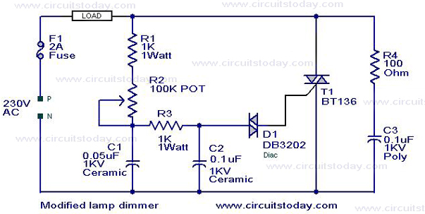
Light Dimmer Circuit TRIAC dimmer circuitCircuitWorking
This is a modification of the Simple Lamp Dimmer/Fan Regulator circuit that was previously posted. The operation of the circuit remains the same as the original; however, it now includes a snubber circuit composed of resistor R4 and capacitor C3...

Simple Triac Circuit Circuit
A triac can be utilized as a line-operated AC power switch that directly controls lamps, heaters, or motors. A brief current pulse into the gate activates the triac, and it remains on until the main current reverses.
A triac, or triode...

Simple Lamp Dimmer/ Fan Regulator Circuit
A fan regulator circuit that can also function as a simple lamp dimmer circuit. This fan speed regulator or light dimmer operates based on power control using a triac.
The fan regulator circuit is designed to control the speed of a...
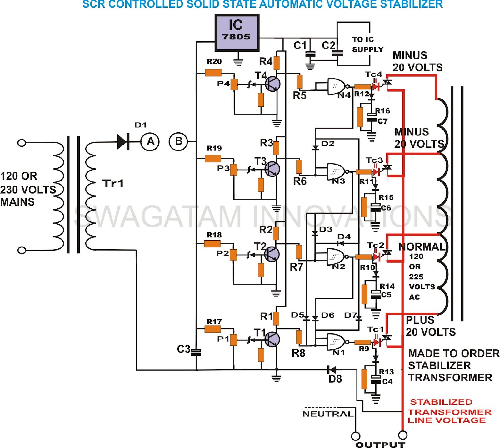
build solid state scrtriac controlled
This unique and hard-to-find triac-controlled AC voltage stabilizer circuit has been specifically designed for efficient voltage stabilization. With a solid-state design, the voltage switching transitions are smooth, resulting in minimal wear and tear. The proposed circuit provides four-step voltage stabilization...

simple TRIAC Light Dimmer
This little circuit can be used to dim lights up to about 350 watts. It uses a simple, standard TRIAC circuit that, in my experience, generates very little heat. Please note that this circuit cannot be used with fluorescent lights....

Simple Electronic Fan Regulator Circuit PCB
The circuit diagram presented is a triac-diac electronic fan regulator designed to reduce power consumption of electric fans, even at low speeds. Traditional resistor-inductor fan regulators tend to generate excess heat, wasting energy when the fan operates at lower speeds,...
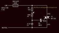
Simple Lamp Dimmer Fan Regulator
The circuit operates by adjusting the firing angle of the Triac. Resistors R1, R2, and capacitor C2 are involved in this process. The firing angle can be modified by changing the value of any of these components, with R1 designated...