


The CUSB-36R Christmas Light Circuit
#Christmas lights
#mains powered
#relays
#programmed
#CUSB-36R
#schematic
#holiday lighting
#LED control
#home decoration
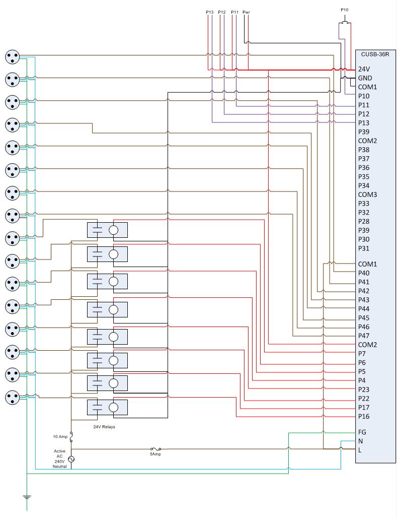
Description: This is the circuit diagram for the Comfile CUSB-36R Programmed Christmas Lights. If it is difficult to read, please contact me via email at [email protected], and I will provide a more detailed schematic. The Comfile CUSB-36R can either drive mains-powered devices directly or control relays to switch mains-powered devices. This circuit diagram features two groups of eight. The ports P40-P47 are directly switched, limiting the total current draw to 5 Amps, which is protected by a 5A fuse in the diagram. It is essential to wire this correctly and verify that the circuit ceases to function when the fuse is removed. An incorrect wiring of the fuse can lead to excessive current draw and potential damage to the circuit. Inputs P11, P12, and P13 are connected to a Cat-5 LAN cable linking to the Velleman K8055, allowing synchronization between the computer and the lights controlled by the CUSB-36R. Additionally, a 24V line powers the relays that the K8055 will close to trigger the P11, P12, and P13 inputs. For economical power sockets, 16 2m Arlec extension cords were purchased, with the plug ends cut off. This design allows the leads to extend out of the box, minimizing the required surface area to accommodate all sockets.
The Comfile CUSB-36R circuit diagram serves as a versatile solution for controlling Christmas lights through a programmed interface. The design incorporates a microcontroller that can manage both direct mains connections and relay-driven outputs, facilitating a wide range of applications. The configuration of two groups of eight ports (P40-P47) enables straightforward control of multiple lighting circuits while ensuring that the current draw does not exceed 5 Amps. This is crucial for maintaining system integrity, and the inclusion of a 5A fuse acts as a safeguard against potential overloads.
The connection of ports P11, P12, and P13 via a Cat-5 LAN cable to the Velleman K8055 adds a layer of complexity, allowing for real-time synchronization of the light patterns with computer software. This setup enhances the user experience by enabling dynamic control of the lighting effects based on programmed sequences or live input. The 24V power line dedicated to the relay operation ensures that the relays can handle the switching of higher voltage devices safely and efficiently.
The innovative use of 2m Arlec extension cords for power sockets exemplifies a cost-effective approach to creating a functional lighting system. By cutting the plug ends, the design retains flexibility and reduces the footprint of the wiring setup, making it easier to integrate into various environments. This circuit diagram not only illustrates the electrical connections but also emphasizes the importance of careful planning and execution to prevent mishaps, such as miswiring, which could lead to circuit failure. Overall, the Comfile CUSB-36R circuit represents a practical and efficient solution for festive lighting control, tailored for ease of use and reliability.This is the circuit diagram for the Comfile CUSB-36R Programmed Christmas Lights. If it is a little hard to read drop me an email at keithsw1@yahoo. com and I will return a more detailed schematic. Basically the Comfile CUSB-36R can either directly drive mains powered devices or it can drive relays to switch mains powered devices. There are two gro ups of 8 in this circuit diagram. I have chosen to switch ports P40-P47 directly. This limits their total current draw to 5Amps which is protected in this diagram by the 5A fuse. Make sure you wire this in correctly and test that when the fuse is removed the circuit stops working. I accidentally miswired my fuse and burnt out one half of my circuit due to too much current draw. The other inputs P11, P12 and P13 are attached to a Cat-5 lan cable which connects to the Velleman K8055 and are used to synch the computer to the lights that are flashed by the CUSB-36R.
There is also a 24V line which is used to power the relays the K8055 will close to trigger the P11, P12 and P13 inputs. To do the power sockets on the cheap I bought 16 2m Arlec extension cords and cut the plug end off it.
This works really well as the leads hang out of the box which means the box does not need a large surface area to hold all the sockets.
The Comfile CUSB-36R circuit diagram serves as a versatile solution for controlling Christmas lights through a programmed interface. The design incorporates a microcontroller that can manage both direct mains connections and relay-driven outputs, facilitating a wide range of applications. The configuration of two groups of eight ports (P40-P47) enables straightforward control of multiple lighting circuits while ensuring that the current draw does not exceed 5 Amps. This is crucial for maintaining system integrity, and the inclusion of a 5A fuse acts as a safeguard against potential overloads.
The connection of ports P11, P12, and P13 via a Cat-5 LAN cable to the Velleman K8055 adds a layer of complexity, allowing for real-time synchronization of the light patterns with computer software. This setup enhances the user experience by enabling dynamic control of the lighting effects based on programmed sequences or live input. The 24V power line dedicated to the relay operation ensures that the relays can handle the switching of higher voltage devices safely and efficiently.
The innovative use of 2m Arlec extension cords for power sockets exemplifies a cost-effective approach to creating a functional lighting system. By cutting the plug ends, the design retains flexibility and reduces the footprint of the wiring setup, making it easier to integrate into various environments. This circuit diagram not only illustrates the electrical connections but also emphasizes the importance of careful planning and execution to prevent mishaps, such as miswiring, which could lead to circuit failure. Overall, the Comfile CUSB-36R circuit represents a practical and efficient solution for festive lighting control, tailored for ease of use and reliability.This is the circuit diagram for the Comfile CUSB-36R Programmed Christmas Lights. If it is a little hard to read drop me an email at keithsw1@yahoo. com and I will return a more detailed schematic. Basically the Comfile CUSB-36R can either directly drive mains powered devices or it can drive relays to switch mains powered devices. There are two gro ups of 8 in this circuit diagram. I have chosen to switch ports P40-P47 directly. This limits their total current draw to 5Amps which is protected in this diagram by the 5A fuse. Make sure you wire this in correctly and test that when the fuse is removed the circuit stops working. I accidentally miswired my fuse and burnt out one half of my circuit due to too much current draw. The other inputs P11, P12 and P13 are attached to a Cat-5 lan cable which connects to the Velleman K8055 and are used to synch the computer to the lights that are flashed by the CUSB-36R.
There is also a 24V line which is used to power the relays the K8055 will close to trigger the P11, P12 and P13 inputs. To do the power sockets on the cheap I bought 16 2m Arlec extension cords and cut the plug end off it.
This works really well as the leads hang out of the box which means the box does not need a large surface area to hold all the sockets.

Christmas Light Driver
This circuit enables a CMOS logic chip, such as a 4017 decode driver, to control a string of Christmas lights or other lighting. The triac should be rated at 200 V and 3 A or higher. The 4017 should be...

Normally-open-and-closed-relays
The phototransistor and photodarlington couplers function as direct current relays in saturated switching, handling currents up to 5 mA and 50 mA, respectively. For applications requiring higher currents or voltage capabilities, supplementary devices are necessary to buffer or amplify the...

Fastest Finger First project
If 12V relays are used, you can replace the 180R resistors R7, R9, R14, R16, R20, R22, R26, and R28 with a wire link (the resistors are only there to limit current if you use 5V relays, of which I...

How to Read a Schematic
Electronic circuits are presented in schematic form. A schematic is essentially a map that illustrates the path of current through various components. Each component is represented by a symbol, typically accompanied by a label or a value, or both. The...

8 input Relays circuit
It is the essential continuity of circuits Sel 8 Sources and Up/Down Sel 8 Sources, but can work and autonomously, collaborating with any suitable circuit of control. The Relay 1-8 can be 6-24v DC. For current of collector of transistors...
schematic diagram graphic arts
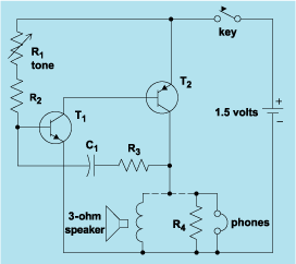
Schematic diagram. A presentation of the element-by-element relationship of all parts of a system.
A schematic diagram serves as a crucial tool in electronic design and engineering, representing the interconnections and relationships between various components within a system. It provides a...
metal detector project circuit
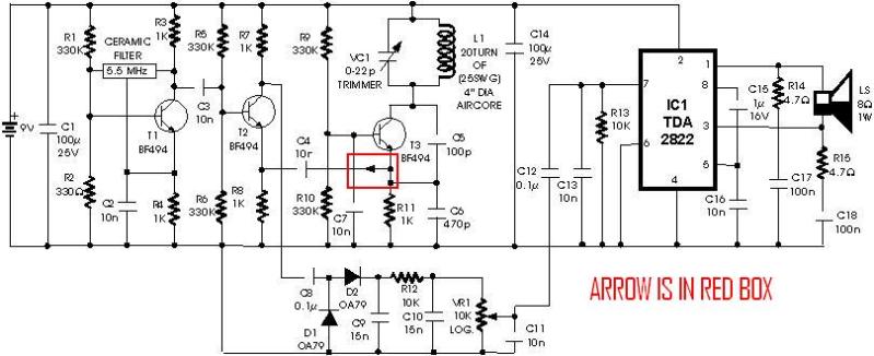
A schematic diagram for a metal detector has been found. The project does not need to be original and can be sourced from the internet. There are several questions regarding this schematic. One query pertains to a small arrow connected...

ELECTRONIC SCHEMATIC CIRCUIT DIAGRAMS
Electronic Schematic Circuit Diagrams Manual PDF Download.
The document provides a comprehensive manual that focuses on electronic schematic circuit diagrams. These diagrams are essential tools for understanding and designing electronic circuits, offering visual representations of circuit components and their interconnections. The...

A Christmas lights circuit
An air bridge after the bullock Phi Beach in Sichuan utilizes direct beam lights. Control is implemented for six buildings with filtered output at specific voltage levels. The system includes a small 4H servant for pressure control, and components such...