


TV by the photosensitive resistor circuit diagram automatic brightness adjustment
#photosensitive resistor
#automatic brightness
#television
#contrast adjustment
#light sensor
#circuit diagram
#potentiometer
#brightness control

Description: The circuit for automatic brightness adjustment in a television utilizes a photosensitive resistor and a contrast potentiometer connected to an intermediate stage. The photosensitive resistor varies its resistance based on light intensity, causing changes in the potential at the intermediate stage. This variation is processed through a decoding circuit, specifically the TA7698AP, to control the adjustments in TV brightness, contrast, and saturation. As the ambient light brightness decreases, the resistance of the photosensitive resistor decreases, resulting in an increase in the potential at the center of the potentiometer.
The automatic brightness adjustment circuit for televisions is designed to enhance viewing comfort by adapting the display settings according to ambient light conditions. It employs a photosensitive resistor, commonly referred to as a light-dependent resistor (LDR), which exhibits a change in resistance based on the intensity of light it is exposed to. This component is critical for detecting surrounding light levels.
The circuit architecture integrates the photosensitive resistor with a contrast potentiometer, which serves as a variable resistor to fine-tune the contrast settings of the television. The connection of these components to an intermediate stage allows for the modulation of the voltage signal based on the light intensity detected by the LDR. As the light intensity increases, the resistance of the LDR decreases, leading to a corresponding increase in voltage at the intermediate stage.
The TA7698AP decoding circuit plays a pivotal role in translating the voltage variations into actionable signals that adjust the television's brightness, contrast, and saturation levels. This IC is designed to process the input from the intermediate stage and output the necessary control signals to the television's display driver circuitry.
In scenarios where ambient light is low, the LDR's resistance decreases significantly, causing an increase in the voltage at the potentiometer's midpoint. This change prompts the TA7698AP to modify the display parameters accordingly, ensuring that the image remains clear and visible without excessive brightness or contrast that could lead to viewer discomfort or eye strain.
Overall, this automatic brightness adjustment circuit exemplifies a practical application of analog electronics in consumer devices, promoting enhanced user experience by automatically adapting display settings to environmental changes. By the photosensitive resistor television automatic brightness adjustment circuit shown in Figure photoresistor and contrast potentiometer connected to the intermediate head. U se photoresistor vary light intensity and the change in resistance characteristics, the potential of the intermediate potential head with different light intensity changes, through decoding circuit TA7698AP control, so the TV brightness, contrast, saturation change accordingly. Light brightness, small GR resistance, potentiometer middle of the first potential rise.
The automatic brightness adjustment circuit for televisions is designed to enhance viewing comfort by adapting the display settings according to ambient light conditions. It employs a photosensitive resistor, commonly referred to as a light-dependent resistor (LDR), which exhibits a change in resistance based on the intensity of light it is exposed to. This component is critical for detecting surrounding light levels.
The circuit architecture integrates the photosensitive resistor with a contrast potentiometer, which serves as a variable resistor to fine-tune the contrast settings of the television. The connection of these components to an intermediate stage allows for the modulation of the voltage signal based on the light intensity detected by the LDR. As the light intensity increases, the resistance of the LDR decreases, leading to a corresponding increase in voltage at the intermediate stage.
The TA7698AP decoding circuit plays a pivotal role in translating the voltage variations into actionable signals that adjust the television's brightness, contrast, and saturation levels. This IC is designed to process the input from the intermediate stage and output the necessary control signals to the television's display driver circuitry.
In scenarios where ambient light is low, the LDR's resistance decreases significantly, causing an increase in the voltage at the potentiometer's midpoint. This change prompts the TA7698AP to modify the display parameters accordingly, ensuring that the image remains clear and visible without excessive brightness or contrast that could lead to viewer discomfort or eye strain.
Overall, this automatic brightness adjustment circuit exemplifies a practical application of analog electronics in consumer devices, promoting enhanced user experience by automatically adapting display settings to environmental changes. By the photosensitive resistor television automatic brightness adjustment circuit shown in Figure photoresistor and contrast potentiometer connected to the intermediate head. U se photoresistor vary light intensity and the change in resistance characteristics, the potential of the intermediate potential head with different light intensity changes, through decoding circuit TA7698AP control, so the TV brightness, contrast, saturation change accordingly. Light brightness, small GR resistance, potentiometer middle of the first potential rise.

Light-sensitive Alarm Project
The circuit detects a sudden shadow on the light sensor and activates a bleeper when this occurs. It is designed to ignore gradual changes in brightness to prevent false alarms. The bleeper operates for a brief duration to conserve battery...

Automatic Brightness Switch
Driving the highway with your high-beam headlights can really increase your visibility, but can be a blinding hazard for other drivers. This simple circuit can be wired into your headlight switch to provide automatic switching between high and low beam...

Amateur Television Transmitter
Although the unit was designed for 2 W operation, the Q6 and Q7 stages and their associated components can be omitted. Approximately 1 to 30 mW of RF can be obtained by link coupling to L9. A complete set of...

Using tap potentiometer loudness circuit
Figure 1.88 illustrates the loudness control circuit utilizing multiple taps on a potentiometer. In Figure (A), the connection is made between the tap and the potentiometer's input, along with the ground. An RC compensation network is employed, where the slide...

Light Activated Switch
The light-activated switch circuit can be used for switching off a particular lamp or group of lamps in response to varying ambient light levels.
The light-activated switch circuit utilizes a light-dependent resistor (LDR) as the primary sensing element to detect ambient...

TDA8340 Television If Amplifier And Demodulator - Nxp Semiconductors
The TDA9813T is an integrated circuit designed for processing vision intermediate frequency (IF) signals and dual frequency modulation (FM) demodulation of sound. It operates with a single reference QSS-IF in television (TV) and video cassette recorder (VCR) applications, specifically supporting...
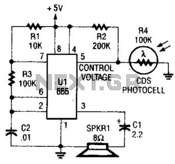
Light-Controlled Oscillator Circuit
This circuit can be utilized as a light detector and potentially as a tool for individuals with visual impairments. The frequency of the oscillator is influenced by the level of illumination received by LDR4.
The circuit operates by employing a Light...

music circuit
This circuit allows for the adjustment of resistance using a potentiometer and the adjustment of capacitance by opening or closing switches. By manipulating the configuration of these switches, various combinations can be achieved to obtain different effective capacitance values. It...

AUDIBLE LIGHT METER
A low light condition on a cadmium sulfide photocell (Radio Shack 276-116) generates a series of clicks in a miniature 8-ohm loudspeaker. As the light intensity increases, these clicks coalesce into an audio tone that escalates in frequency with rising...