


Two mode night light circuit - WorkingCircuit DIagram
#night light
#two mode
#circuit diagram
#LED
#automatic control
#light sensor
#energy saving
#home automation
#diy electronics
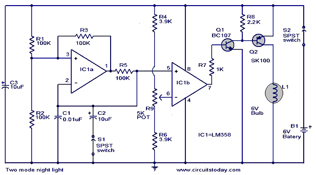
Description: The operation and circuit diagram of a two-mode night light circuit are provided below.
The two-mode night light circuit is designed to operate in two distinct lighting modes, typically offering a choice between a standard brightness setting and a dimmer, energy-saving mode. This circuit can be particularly useful in environments such as bedrooms or hallways, where a soft light is preferred during nighttime hours.
The core components of the circuit include a light-emitting diode (LED) for illumination, a resistor to limit the current flowing through the LED, and a switch mechanism that allows the user to toggle between the two modes. Additionally, a transistor may be used to amplify the control signal from the switch, enabling the circuit to handle the different brightness levels effectively.
In the standard mode, the LED is powered directly, providing maximum brightness. In the dim mode, the circuit could utilize a resistor in series with the LED to reduce the current, resulting in a lower light output. Alternatively, a pulse-width modulation (PWM) approach could be employed to control the brightness dynamically, allowing for a more efficient power usage.
The schematic diagram typically illustrates the arrangement of these components, with clear indications of the power supply connections, the orientation of the LED, and the placement of the switch. Proper attention to the values of the resistors and the specifications of the LED is crucial to ensure optimal performance and longevity of the circuit.
In summary, the two-mode night light circuit is a practical solution for providing adjustable lighting in low-light environments, combining functionality with energy efficiency.The working and circuit diagram of a two mode night light circuit is given below..
The two-mode night light circuit is designed to operate in two distinct lighting modes, typically offering a choice between a standard brightness setting and a dimmer, energy-saving mode. This circuit can be particularly useful in environments such as bedrooms or hallways, where a soft light is preferred during nighttime hours.
The core components of the circuit include a light-emitting diode (LED) for illumination, a resistor to limit the current flowing through the LED, and a switch mechanism that allows the user to toggle between the two modes. Additionally, a transistor may be used to amplify the control signal from the switch, enabling the circuit to handle the different brightness levels effectively.
In the standard mode, the LED is powered directly, providing maximum brightness. In the dim mode, the circuit could utilize a resistor in series with the LED to reduce the current, resulting in a lower light output. Alternatively, a pulse-width modulation (PWM) approach could be employed to control the brightness dynamically, allowing for a more efficient power usage.
The schematic diagram typically illustrates the arrangement of these components, with clear indications of the power supply connections, the orientation of the LED, and the placement of the switch. Proper attention to the values of the resistors and the specifications of the LED is crucial to ensure optimal performance and longevity of the circuit.
In summary, the two-mode night light circuit is a practical solution for providing adjustable lighting in low-light environments, combining functionality with energy efficiency.The working and circuit diagram of a two mode night light circuit is given below..
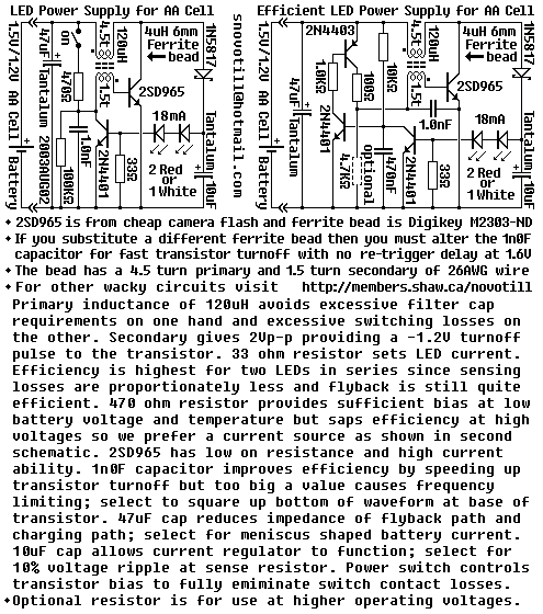
LED power supply
Efficiency can be increased by using a germanium transistor at the 33 ohm current sense resistor, and by using a proper torroid core in place of the crappy ferrite bead. Single AA cell powers two LEDs at constant current.
The circuit...
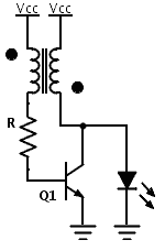
LED Boost converter Joule Thief circuit
Previously, a boost circuit was tested that enables the powering of a 3 V LED using a discharged battery (approximately 1 V or lower). This circuit consists of a single transistor, one resistor, and a small transformer with a 1:1...

flash light electronic diagram
This circuit causes an LED to blink every half second. The duration of the blinking can be modified by changing the value of capacitor C1. Additionally, up to 18 more LEDs can be connected to this circuit, allowing for a...

Constant LED power circuit
An LED is usually a series resistor needed to ensure that the LED does not get too much power. The disadvantage of such resistance is that the current through the LED and thus the brightness changes as the voltage changes....

Constant Current LED Tester
Most circuits utilize a 5 V regulated power supply for microcontrollers and sensors, as 8-bit microcontrollers operate efficiently at this voltage. The 5 V supply is adequate for powering white LEDs, thus the specific voltage requirements of individual LEDs are...

Economical Desk Lamp For Camping
This LED lamp was originally designed for use on a budget solar-charged 12V electrical system. It is bright enough for comfortable reading at night and features constant LED brightness with diminishing battery voltage. The circuit uses six high-brightness white LEDs...

Light Sensor Switch Circuit
This light sensor switch circuit enables the automatic activation of a lamp when ambient light levels are low (such as during nightfall) and keeps the lamp illuminated for a specified duration. When transistors T4 and T5 are activated, the relay's...

dancing lights circuit diagram
This circuit serves as a decorative element or indicator, featuring adjustable flashing or dancing speeds of LEDs and the ability to create various light patterns. It consists of two astable multivibrators: one formed by transistors T1 and T2, and the...

Electronics Circuits Reference Archive Audio LED VU meter
The circuit is designed to operate with an audio power amplifier that uses 18V-0V-18V power rails. The specific voltage is not critical, but the feedback is referenced to an LED chain connected to a 12V rail, necessitating a separate stabilizer...