


Two-wire Lamp Flasher
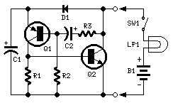
Description: Ideal to operate 3 to 24V DC existing on-circuit lamps. LED operation is also possible. This circuit was designed to provide that continuous light lamps already wired into a circuit become flashing. Simply insert the circuit between existing lamp and negative supply. Especially suited for car or panel pilot lights, this device can drive lamps up to 10W. More: * Break lamp(s) to negative supply connection(s), then insert the circuit between existing lamp(s) connection(s) and negative supply (respecting polarities!). * C1 value can be varied from 100 to 1000µF or higher, in order to change flashing frequency.
This circuit functions as a flashing light controller for existing DC lamps operating within a voltage range of 3 to 24V. It is particularly advantageous for applications involving automotive lighting or panel indicators, where the desire is to convert a steady light into a flashing one. The circuit is designed to be inserted between the lamp and the negative supply line, effectively interrupting the current path to create the desired flashing effect.
The primary component responsible for the flashing action is a capacitor, designated as C1. The capacitance value of C1 can be adjusted from 100µF to 1000µF or even higher, allowing for customization of the flashing frequency. A larger capacitance will result in a slower flashing rate, while a smaller capacitance will produce a faster flashing rate. This flexibility enables the circuit to be tailored to specific user requirements or preferences.
In practical implementation, the circuit requires careful attention to the polarity of connections. It is crucial to respect the correct orientation when connecting the circuit to ensure proper operation and to prevent damage to the components involved. The circuit can drive lamps with a maximum power rating of up to 10W, making it suitable for a variety of lighting applications.
Overall, this flashing lamp circuit represents a simple yet effective solution for enhancing the functionality of existing lighting systems, transforming standard lamps into attention-grabbing indicators.Ideal to operate 3 to 24V DC existing on-circuit lamps LED operation is also possible. This circuit was designed to provide that continuous light lamps already wired into a circuit, become flashing. Simply insert the circuit between existing lamp and negative supply. Especially suited for car or panel pilot lights, this device can drive lamps up to 10W. * Break lamp(s) to negative supply connection(s), then insert the circuit between existing lamp(s) connection(s) and negative supply (respecting polarities!). * C1 value can be varied from 100 to 1000µF or higher, in order to change flashing frequ
This circuit functions as a flashing light controller for existing DC lamps operating within a voltage range of 3 to 24V. It is particularly advantageous for applications involving automotive lighting or panel indicators, where the desire is to convert a steady light into a flashing one. The circuit is designed to be inserted between the lamp and the negative supply line, effectively interrupting the current path to create the desired flashing effect.
The primary component responsible for the flashing action is a capacitor, designated as C1. The capacitance value of C1 can be adjusted from 100µF to 1000µF or even higher, allowing for customization of the flashing frequency. A larger capacitance will result in a slower flashing rate, while a smaller capacitance will produce a faster flashing rate. This flexibility enables the circuit to be tailored to specific user requirements or preferences.
In practical implementation, the circuit requires careful attention to the polarity of connections. It is crucial to respect the correct orientation when connecting the circuit to ensure proper operation and to prevent damage to the components involved. The circuit can drive lamps with a maximum power rating of up to 10W, making it suitable for a variety of lighting applications.
Overall, this flashing lamp circuit represents a simple yet effective solution for enhancing the functionality of existing lighting systems, transforming standard lamps into attention-grabbing indicators.Ideal to operate 3 to 24V DC existing on-circuit lamps LED operation is also possible. This circuit was designed to provide that continuous light lamps already wired into a circuit, become flashing. Simply insert the circuit between existing lamp and negative supply. Especially suited for car or panel pilot lights, this device can drive lamps up to 10W. * Break lamp(s) to negative supply connection(s), then insert the circuit between existing lamp(s) connection(s) and negative supply (respecting polarities!). * C1 value can be varied from 100 to 1000µF or higher, in order to change flashing frequ
LED Battery indicator
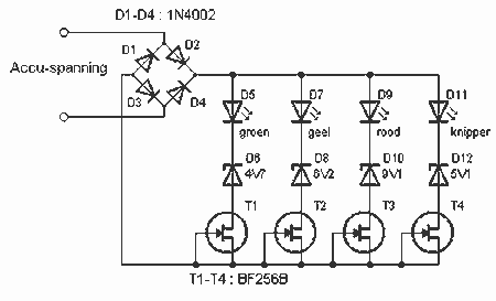
This battery allows the indicator to the car battery voltage monitor. The indicator has four LEDs which indicate power. The more LEDs, the higher the voltage. The last LED is a flashing LED. It comes on when the accuspaning limit...

Light Chaser I
Up to 100 lights, LEDs, or optocoupler triac circuits can be sequentially activated by this circuit. One (U1) 4017 decodes and sequences 10 LEDs, whose common anode is returned through a second (U2) CD4017, which counts at one-tenth of the...
High Bright LED Emergency Lamp
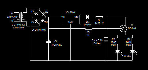
This is a high-efficiency emergency lamp that utilizes high-brightness white LEDs. It automatically activates during power failures and deactivates when power is restored.
The emergency lamp circuit is designed to provide reliable illumination during power outages, utilizing high-brightness white LEDs for...

LED Flashlight circuit with MAX1811
White LEDs have a rated current at a voltage drop of about 3.3 to 3.4 V. It is ideal to be powered from the battery voltage which is slightly larger. Then there is the best energy used. In this I...

led tube light using transformer
The use of white LEDs for home illumination is gaining popularity due to their high power efficiency. The diagram illustrates a simple circuit configuration that consists of multiple LEDs arranged in both series and parallel. In the LED tube light...

LED torch using NSI45090JDT4G constant current regulator
A very simple LED torch can be designed using the NSI45090JDT4G adjustable constant current regulator (CCR) from ON Semiconductor, utilizing very few external components. The NSI45090JDT4G device provides a cost-effective solution for regulating current in LEDs. This constant current regulator...

Super Led Flasher Circuit
The super LED flasher consists of two complete LED flasher circuits integrated onto a single circuit board. The first LED flasher is comprised of IC1 and LEDs D1 and D2. IC1 is a 555 timer IC configured as an astable...

Regulated LED Lamp
The LM317L and resistor act as a current regulator set to 40ma. Current flows from the battery through one pair of LEDs, through the regulator, through the other pair of LEDs, and back to the battery. The capacitor filters out...

Light that screen!
The circuit is quite simple and can be utilized as an introductory hardware modification for the NXT platform. A white LED (D1) is powered through a 150-ohm resistor (R1) using the 4.3V power supply from the NXT. The forward voltage...