


With a CD4069 make fantastic light
#CD4069
#LED
#rectifier
#AC to DC
#light control
#bridge diode
#full-wave
#pulsating DC
#electric lights

Description: The circuit consists of a bridge diode rectifier formed by diodes VD1 to VD4, which converts 220V AC into pulsating DC. This DC is utilized to power red, green, and blue electric lights (H1 to H3). Additionally, a resistor R10 is used for bucking, while VD5 acts as a regulator and VD6 provides isolation. Capacitor C7 is employed for power supply filtering. The CD4069 integrated circuit functions as an inverter, containing six inverters organized into three pairs, forming an ultra-low frequency oscillator with an oscillation frequency of approximately 1 to 2 Hz. Upon startup, the output generates positive square wave pulses that pass through resistors R4 to R6, activating the corresponding transistors (VT1 to VT3). When these transistors are turned on, they trigger the associated silicon-controlled rectifiers (SCRs, VS1 to VS3), illuminating the respective lights (H1 to H3). After the pulse, the transistors turn off, causing the SCRs to deactivate and the lights to extinguish. Consequently, the lights flash in sync with the oscillator frequency. The three oscillator circuits share identical resistance and capacitance values; however, slight variations in the discrete element parameters result in minor differences in oscillation frequency and phase. This randomness creates a visually appealing effect when the three colored lights are viewed through a translucent frosted or opal glass shade, producing a blend of colors based on the principles of additive color mixing.
The circuit design is centered around a bridge rectifier configuration, which effectively converts the alternating current (AC) supply into a direct current (DC) output suitable for driving the light-emitting diodes (LEDs) or incandescent bulbs. The bridge rectifier, composed of diodes VD1 through VD4, ensures that both halves of the AC waveform contribute to the output, resulting in a smoother DC signal. The inclusion of a bucking resistor, R10, serves to limit the current flowing into the subsequent components, ensuring that the voltage levels remain within safe operating limits.
The voltage regulation is achieved through the use of diode VD5, which provides a stable output voltage by preventing voltage spikes that could damage the LED components. VD6 is included for isolation purposes, protecting the circuit from potential feedback or noise from the power supply. Capacitor C7 plays a critical role in filtering out any remaining ripple from the rectified DC, ensuring that the power supply to the CD4069 IC is clean and stable.
The CD4069 is a quad inverter CMOS IC that has been configured to create an ultra-low frequency oscillator. The pairing of inverters allows for the generation of square wave signals, which are essential for controlling the timing of the light activation. The oscillation frequency is carefully designed to be in the range of 1 to 2 Hz, which is slow enough to create a noticeable flashing effect without being overly distracting.
The resistors R4 to R6 are strategically placed to control the current flowing into the base of the transistors VT1 to VT3. When the oscillator output goes high, it turns on the corresponding transistor, which in turn activates the SCRs. This allows the current to flow through the respective lights (H1 to H3), causing them to illuminate. The rapid switching of the transistors and SCRs creates a pulsing effect, resulting in the lights flashing in a rhythmic pattern.
The design also takes advantage of the natural variation in component tolerances, which leads to slight differences in the frequency and phase of the oscillators. This randomness contributes to the aesthetic appeal of the lighting display, especially when viewed through a frosted or opal glass cover. The blending of the primary colors—red, green, and blue—creates a visually dynamic experience, showcasing the principles of color mixing in a practical application. Overall, this circuit exemplifies an effective approach to creating an engaging lighting effect using basic electronic components.FIG VDI ~ VD4 form a bridge diode rectifier, a full-wave transform the 220V AC pulsating DC, all the way for the red, green and blue (ie HI ~ H3) electric lights, another way t hen by Rl0 buck, VD5 regulator and VD6 isolation and capacitor C7 CD4069 integrated circuit A power supply filtering. CD4069 inverter in six every two inverters (such as an inverter I and ) consisting of a ultra-low frequency oscillator, a total structure into three oscillators, their oscillation frequency is about 1 ~ 2Hz or so, when the oscillation Start-up time, the output terminal positive square wave pulse, through resistor R4-R6 so that the corresponding gap transistor VTI ~ VT3 conduction, when the transistor is turned on, its corresponding SCR (VSI ~ VS3) on opened, the corresponding lights (H1-H3) on the light-emitting, after the pulse, the transistor cut stop, SCR off, lights out.
The lights will flash with the nozzle oscillation frequency of light. Three oscillator circuit resistance values of capacitance elements is identical, but the discrete element parameters, the parameters are different more or less total, the oscillator produces square wave oscillator frequency and phase are there are small differences, the same time light bulb which is entirely random. Such as in the production of the three light bulbs emitted onto the same piece of translucent frosted glass or opal glass shade, we see mixed light will be emitted three lights, according to the principles of its three primary color changing, very good looking.
The circuit design is centered around a bridge rectifier configuration, which effectively converts the alternating current (AC) supply into a direct current (DC) output suitable for driving the light-emitting diodes (LEDs) or incandescent bulbs. The bridge rectifier, composed of diodes VD1 through VD4, ensures that both halves of the AC waveform contribute to the output, resulting in a smoother DC signal. The inclusion of a bucking resistor, R10, serves to limit the current flowing into the subsequent components, ensuring that the voltage levels remain within safe operating limits.
The voltage regulation is achieved through the use of diode VD5, which provides a stable output voltage by preventing voltage spikes that could damage the LED components. VD6 is included for isolation purposes, protecting the circuit from potential feedback or noise from the power supply. Capacitor C7 plays a critical role in filtering out any remaining ripple from the rectified DC, ensuring that the power supply to the CD4069 IC is clean and stable.
The CD4069 is a quad inverter CMOS IC that has been configured to create an ultra-low frequency oscillator. The pairing of inverters allows for the generation of square wave signals, which are essential for controlling the timing of the light activation. The oscillation frequency is carefully designed to be in the range of 1 to 2 Hz, which is slow enough to create a noticeable flashing effect without being overly distracting.
The resistors R4 to R6 are strategically placed to control the current flowing into the base of the transistors VT1 to VT3. When the oscillator output goes high, it turns on the corresponding transistor, which in turn activates the SCRs. This allows the current to flow through the respective lights (H1 to H3), causing them to illuminate. The rapid switching of the transistors and SCRs creates a pulsing effect, resulting in the lights flashing in a rhythmic pattern.
The design also takes advantage of the natural variation in component tolerances, which leads to slight differences in the frequency and phase of the oscillators. This randomness contributes to the aesthetic appeal of the lighting display, especially when viewed through a frosted or opal glass cover. The blending of the primary colors—red, green, and blue—creates a visually dynamic experience, showcasing the principles of color mixing in a practical application. Overall, this circuit exemplifies an effective approach to creating an engaging lighting effect using basic electronic components.FIG VDI ~ VD4 form a bridge diode rectifier, a full-wave transform the 220V AC pulsating DC, all the way for the red, green and blue (ie HI ~ H3) electric lights, another way t hen by Rl0 buck, VD5 regulator and VD6 isolation and capacitor C7 CD4069 integrated circuit A power supply filtering. CD4069 inverter in six every two inverters (such as an inverter I and ) consisting of a ultra-low frequency oscillator, a total structure into three oscillators, their oscillation frequency is about 1 ~ 2Hz or so, when the oscillation Start-up time, the output terminal positive square wave pulse, through resistor R4-R6 so that the corresponding gap transistor VTI ~ VT3 conduction, when the transistor is turned on, its corresponding SCR (VSI ~ VS3) on opened, the corresponding lights (H1-H3) on the light-emitting, after the pulse, the transistor cut stop, SCR off, lights out.
The lights will flash with the nozzle oscillation frequency of light. Three oscillator circuit resistance values of capacitance elements is identical, but the discrete element parameters, the parameters are different more or less total, the oscillator produces square wave oscillator frequency and phase are there are small differences, the same time light bulb which is entirely random. Such as in the production of the three light bulbs emitted onto the same piece of translucent frosted glass or opal glass shade, we see mixed light will be emitted three lights, according to the principles of its three primary color changing, very good looking.

R/C Airplane LED Flasher
This was designed to flash a pair of LEDs to be mounted on the wing tips of a Parkzone Citabria R/C (remote control) airplane. The unmodified Parkzone Citabria only weighs 20 grams (about 0.7 oz), so weight, and therefore the...
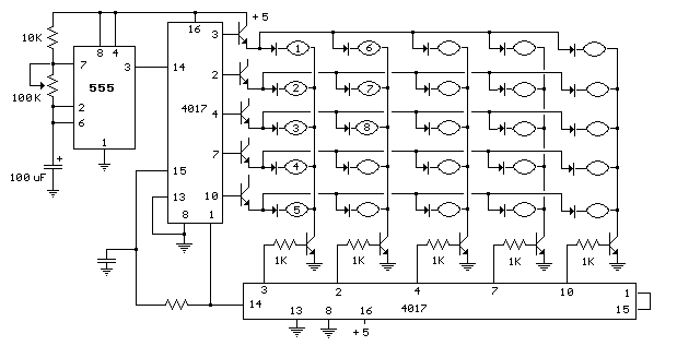
25 LED Sequencer schematic
This circuit is same as the above setup to drive 25 small Xmas lights. The lights operate at about 200mA and 3 volts. The supply voltage is set to 5 volts and the 4017 counter output will drop about a...

Flashing Eyes
This circuit is designed as a humorous Halloween gadget. It is intended to be placed at the back of a badge or pin featuring a typical Halloween character image, such as a pumpkin, skull, black cat, witch, or ghost. Two...

1 5 hour lamp fader sunset lamp
The sunset lamp activates at full brightness and gradually dims over a duration of 1.5 hours, remaining off until the power is reset.
The sunset lamp circuit is designed to simulate the natural fading of sunlight, providing a calming effect as...
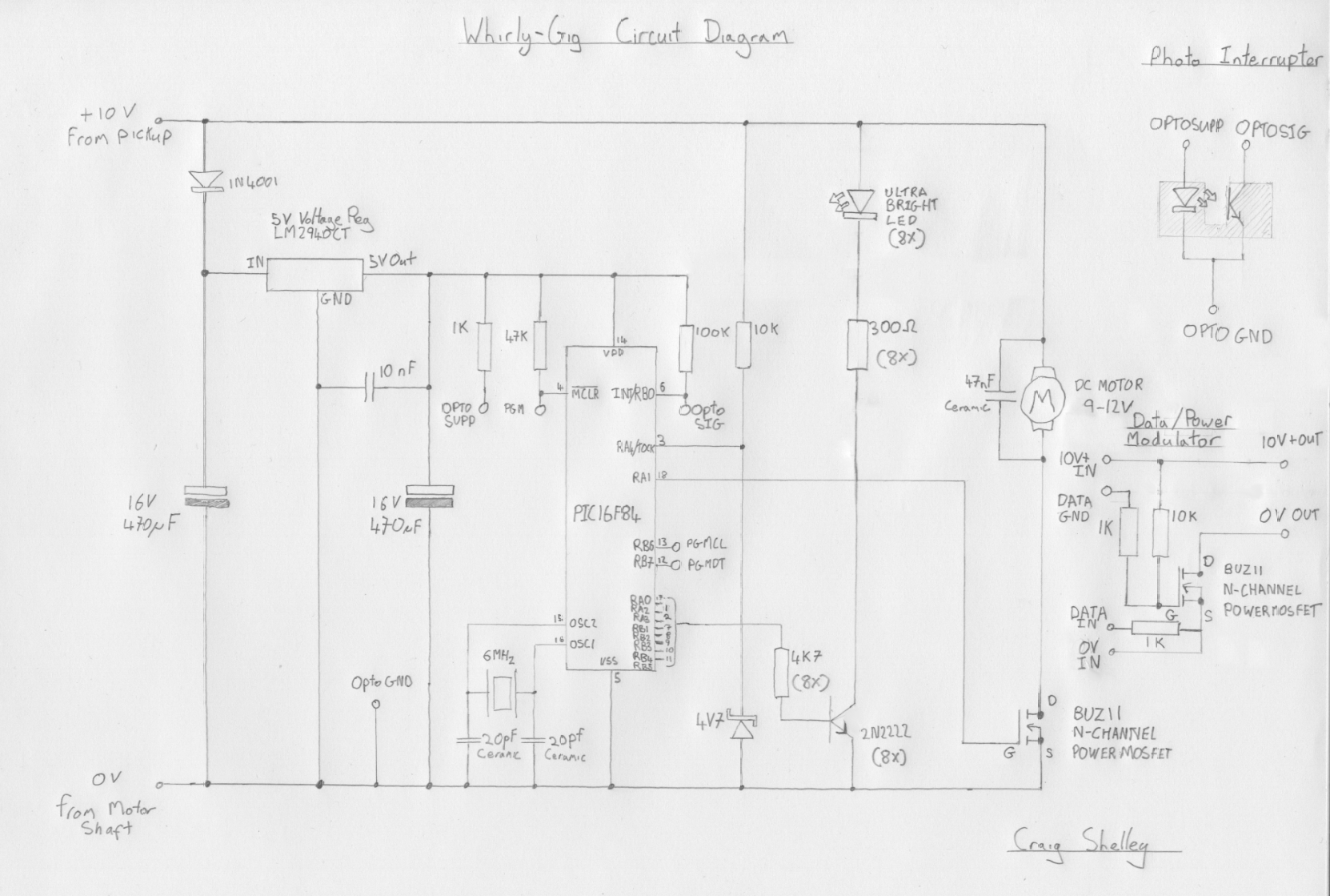
WhirlyGIG
This project employs a technique similar to existing products, allowing for the continuous display of text using a high-speed rotor and a strip of LEDs. The term "WhirlyGig" is derived from the word "whirl," which means to spin, and the...

led flasher circuit schematic inside
Build a circuit that will flash five pairs of LEDs at variable rates. To achieve this, a circuit utilizing five NE555 timers has been designed. Trim pots will be used to control the variable flash rate. Assistance is needed in...

Need Help: Wiring LEDs with 2 source voltages
A series of LEDs is intended to display at two brightness levels, and there is uncertainty regarding the proper wiring. This setup is for additional running lights and brake lights on a bicycle. When using the series LED calculator, it...
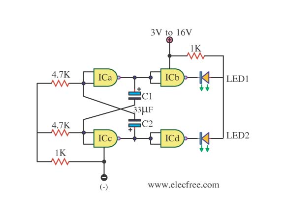
The simple LED Flasher by IC 4011
This is simply a LED flasher circuit that is suggested for construction. However, it is important to understand the use of transistors, which can be challenging when learning about digital electronics.
The LED flasher circuit operates by utilizing a basic astable...

Mains operated led Lamp
This circuit operates 25 LEDs powered by a mains supply of 230V. A fluorescent lamp adapter was acquired from a scrap dealer for ease of disassembly.
The circuit consists of a series of 25 light-emitting diodes (LEDs) arranged to operate from...