


Xenon Strobe Light 110V by SCR
#xenon strobe
#SCR
#flashing light
#VR1
#high brightness
#110V
#blink control
#light intensity
#strobe effect
#adjustable speed

Description: This is a Xenon Strobe Light circuit that utilizes a Xenon tube to produce various brightness levels. The blinking speed can be finely adjusted to be fast or slow using VR1. The circuit incorporates a Silicon Controlled Rectifier (SCR).
The Xenon Strobe Light circuit is designed to generate high-intensity flashes of light, making it suitable for applications such as photography, visual effects, and signaling. The core component, the Xenon tube, operates by ionizing gas within the tube, allowing it to produce a bright flash when a high voltage is applied.
The circuit's operation begins with the charging of a capacitor, which stores energy until it reaches a predetermined voltage. At this point, the SCR is triggered, allowing the stored energy to discharge rapidly through the Xenon tube, resulting in a bright flash. The brightness of the flash can be adjusted by varying the charge voltage, which is controlled through a variable resistor (VR1). This feature enables the user to select the desired intensity of the light output.
In addition to brightness control, the blinking speed can be modified by adjusting the timing components in the circuit. This typically involves changing the values of resistors and capacitors associated with the SCR trigger circuit, allowing for a wide range of flashing rates from rapid strobe effects to slower, more pronounced flashes.
The circuit may also include additional components such as diodes for protection against back EMF, which can potentially damage the SCR or other sensitive components. A power supply is necessary to provide the required voltage for the Xenon tube, which is typically in the range of 300 to 400 volts, depending on the specific tube used.
Overall, the Xenon Strobe Light circuit is a versatile and effective solution for generating high-intensity flashes of light, with adjustable brightness and blinking speed, suitable for various applications in both professional and hobbyist settings.This is Xenon Strobe Light circuit, model continual use a tube Xenon at give many brightnesses. By can fine blink fast or slow get , with VR1. By have SCR.
The Xenon Strobe Light circuit is designed to generate high-intensity flashes of light, making it suitable for applications such as photography, visual effects, and signaling. The core component, the Xenon tube, operates by ionizing gas within the tube, allowing it to produce a bright flash when a high voltage is applied.
The circuit's operation begins with the charging of a capacitor, which stores energy until it reaches a predetermined voltage. At this point, the SCR is triggered, allowing the stored energy to discharge rapidly through the Xenon tube, resulting in a bright flash. The brightness of the flash can be adjusted by varying the charge voltage, which is controlled through a variable resistor (VR1). This feature enables the user to select the desired intensity of the light output.
In addition to brightness control, the blinking speed can be modified by adjusting the timing components in the circuit. This typically involves changing the values of resistors and capacitors associated with the SCR trigger circuit, allowing for a wide range of flashing rates from rapid strobe effects to slower, more pronounced flashes.
The circuit may also include additional components such as diodes for protection against back EMF, which can potentially damage the SCR or other sensitive components. A power supply is necessary to provide the required voltage for the Xenon tube, which is typically in the range of 300 to 400 volts, depending on the specific tube used.
Overall, the Xenon Strobe Light circuit is a versatile and effective solution for generating high-intensity flashes of light, with adjustable brightness and blinking speed, suitable for various applications in both professional and hobbyist settings.This is Xenon Strobe Light circuit, model continual use a tube Xenon at give many brightnesses. By can fine blink fast or slow get , with VR1. By have SCR.

Scr-ring-counter
One lamp at a time is lit in the string to give the appearance of a moving point of light. More: The ring counter circuit.
The described circuit utilizes a ring counter configuration to create a sequential lighting effect in which...

Normally closed contact burglar alarm circuit diagram
The circuit schematic presented in Figure 1 consists of an SCR, R1, and an AN SCR trigger switch circuit, along with an analog circuit composed of IC1, R2, VT1, VT2, and a BL siren. Typically, the circuit is designed to...

build varying brightness ac lamp circuit
A varying brightness AC lamp circuit utilizes a silicon-controlled rectifier (SCR) to gradually adjust the intensity of a 120-volt light bulb by controlling the duration of AC line voltage applied to the lamp during each half cycle. The circuit is...

120Ac Shimmering Light Circuit
This circuit allows any standard household bulb to shimmer or blink. It is compatible with incandescent lights up to 200 W and operates on standard 120 Vac. The circuit employs a silicon-controlled rectifier (SCR) to create the shimmering effect. One...

Dc static switch
This circuit is a static SCR switch designed for use in a DC circuit. When a low-power signal is applied to the gate of SCR1, this SCR is triggered, allowing voltage to be applied to the load. The right plate...

SCR And Triac Triggering Circuit With A Positive Power Supply
The output current of the control circuit must be amplified when the gate current needed to trigger the device exceeds the output current of the control circuit.
To achieve the amplification of the control circuit output current, a suitable transistor configuration...
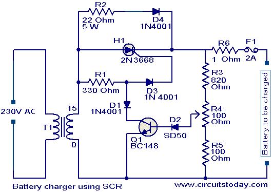
Battery charger circuit using SCR
A simple battery charger based on SCR is presented. The SCR rectifies the AC mains voltage to charge the battery. When the battery connected to the charger is discharged, the battery voltage decreases, inhibiting the forward bias voltage from reaching...

zero voltage switching
The SCR coupler circuit offers increased sensitivity to input signals as demonstrated. This enables the utilization of the more economical 4N39 (H11C3) with the drive currents exceeding 7 mA provided by the input circuit.
The SCR coupler circuit is designed to...

Simple DC power delay circuit
The circuit diagram presented is of a straightforward DC power delay circuit utilizing a silicon-controlled rectifier (SCR). This circuit is quite useful and can be applied in various scenarios. The operation of this circuit is uncomplicated. Upon the application of...