


1 KHz Synchronous Detector
#synchronous detector
#1 KHz
#signal measurement
#noise reduction
#RS-232
#ELF signals
#RF
#optical applications
#microvolts

Description: This circuit employs a synchronous demodulator to separate a 1 KHz signal from noise and measures the amplitude of the 1 kHz signals once a second at about 60 microvolts per count then sends the measurements via an RS-232 interface for further processing or display. An LED on the board also lights when the measured signal exceeds a preset threshold. This experiment was started when I took an interest in receiving ELF wireless signals. It also has applications in optics and high frequency RF, or for that matter, any place one needs to measure a tiny signal, of which the frequency and phase are known, in the presence of noise.
With the addition of a preamplifier based on the LM324, the sensitivity of this circuit was easily extended to a sensitivity to 160 nanovolts per count. That an LM324 is used with little in the way of noise on the output testifies to the value of using this kind of detector. There are several sophisticated references on the web that describe how synchronous detectors work, so here I will only give a light overview and go into some specifics of this implementation.
The idea is to multiply the input signal by the output of a local oscillator that is synchronized with the expected signal, and integrate the result. Imagine a square wave being fed into the signal input of the multiplier and a synchronized square wave being fed into the local oscillator input of the multiplier. If the local oscillator is synchronized such that they are perfectly matched in phase, then the output of the multiplier will be positive when the incoming signal and the local oscillator are positive and the output will also be positive when the inputs are negative (negative x negative = positive) this is actually a full wave rectifier when both signals are synchronized and in the proper phase with one another. The signals fed into the integrator charge the .047 uf capacitor in the integrator. After 999 cycles of the 1 kHz sampling signal, U3C is turned on and the capacitor is discharged with a constant current (1.8V/7.5K = 240 microamps), producing a linear positive-going ramp at 5,106 volts/second on the output of U2C. While the output of U2 is ramping up toward the 1.8 volt reference, the AT90S2313 sits in a loop, incrementing a counter every 1.25 microseconds, until the comparator on the AT90S2313 changes state, indicating that the ramp on U2C has reached the 1.8 volt reference voltage. The maximum count for this measurement is 127 to limit the time spent in the measurement to less than the 250 microsecond interrupt interval. Thus, a 7 bit measurement is made in 160 microseconds or less, and is completed within a single 250 microsecond interrupt interval.
The rate of discharge of the integrating capacitor during the measurement phase is set by the current into the node, 1.8 volts/7.5 k = 240 microamps, divided by the .047 uf capacitance, which gives a 5100 volt/second voltage ramp. The A/D conversion sensitivity is therefore 1.25 us/count X 5100 volts/second = 6.375 millivolts per count.
In theory, signals at the proper frequency are presented as DC to the integrator and all other frequencies average out to zero. In practice, this circuit uses square waves to perform the modulation, so it is susceptible to odd harmonics of the sampling frequency, so it is sensitive to 3 kHz, 5 kHz, 7 kHz..., so an analog filter ahead of the detector can be useful if it is important to reject these frequencies.
The circuit can be broken down into several key components. The synchronous demodulator is the heart of the system, utilizing a multiplier IC to perform the signal mixing. A square wave local oscillator, typically generated by a 555 timer or similar device, is synchronized to the 1 kHz signal. The output of the multiplier is then fed into an integrator circuit, which averages the output over time. The LM324 operational amplifier serves as a preamplifier to boost the input signal to a usable level before demodulation.
The output of the integrator is monitored by a microcontroller, such as the AT90S2313, which handles the counting of the ramp voltage and ultimately converts this into a digital format via an ADC. The RS-232 interface facilitates communication with external devices for data logging or display. The LED indicator provides a visual cue for when the signal exceeds the threshold, enhancing user interaction with the system.
For practical implementation, attention should be given to the layout of the PCB to minimize noise pickup and ensure stable operation, especially when dealing with low-level signals. Proper grounding techniques and shielding may also be necessary to maintain the integrity of the measurements in noisy environments.This circuit employs a synchronous demodulator to separate a 1 KHz signal from noise and measures the amplitude of the 1 kHz signals once a second at about 60 microvolts per count then sends the measurements via an RS-232 interface for further processing or display. An LED on the board also lights when the measured signal exceeds a preset threshold. This experiment was started when I took an interest in receiving ELF wireless signals. It also has applictions in optics and high frequency RF, or for that matter, any place one needs to measure a tiny signal, of which the frequency and phase are known, in the presence of noise.
With the addition of a preamplifier based on the LM324, the sensitivity of this circuit was easily extended to a sensitivity to 160 nanovolts per count. That an LM324 is used with little in the way of noise on the output testifies to the value of using this kind of detector.
There are several sophisticated references on the web that describe how synchronous detectors work, so here I will only give a light overview and go into some specifics of this implementation. The idea is to multiply the input signal by the output of a local oscillator that is synchronized with the expected signal, and integrate the result.
Imagine a square wave being fed into the signal input of the multiplier and a synchronized square wave being fed into the local oscillator input of the multiplier. If the local oscillator is synchronized such that they are perfectly matched in phase, then the output of the multiplier will be positive when the incoming signal and the local oscillator are positive and the output will also be positive when the inputs are negative (negative x negative = positive) this is actually a full wave rectifier when both signals are synchronized and in the proper phase with one another.
The signals fed into the integrator charge the .047 uf capacitor in the integrator. After 999 cycles of the 1 kHz sampling signal, U3C is turned on and the capacitor is discharged with a constant current (1.8V/7.5K = 240 microamps), producing a linear positive-going ramp at 5,106 volts/second on the output of U2C. While the output of U2 is ramping up toward the 1.8 volt reference, the AT90S2313 sits in a loop, incrementing a counter every 1.25 microseconds, until the comparitor on the AT90S2313 changes state, indicating that the ramp on U2C has reached the 1.8 volt reference voltage.
The maximum count for this measurement is 127 to limit the time spent in the measurement to less than the 250 microsecond interrupt interval. Thus, a 7 bit measurement is made in 160 microseconds or less, and is completed within a single 250 microsecond interrupt interval.
The rate of discharge of the integrating capacitor during the measurement phase is set by the current into the node, 1.8 volts/7.5 k =240 microamps, divided by the .047 uf capacitance, which gives a 5100 volt/second voltage ramp. The A/D conversion sensitivity is therefore 1.25 us/count X 5100 volts/second = 6.375 millivolts per count.
In theory, signals at the proper frequency are presented as DC to the integrator and all other frequencies average out to zero. In practice, this circuituses square waves to perform the modulation, so it is susceptible to odd harmonics of the sampling frequency, so it is sensitive to 3 kHz, 5 kHz, 7 kHz..., so an analog filter ahead of the detector can be useful if it is important to reject these frequencies.
With the addition of a preamplifier based on the LM324, the sensitivity of this circuit was easily extended to a sensitivity to 160 nanovolts per count. That an LM324 is used with little in the way of noise on the output testifies to the value of using this kind of detector. There are several sophisticated references on the web that describe how synchronous detectors work, so here I will only give a light overview and go into some specifics of this implementation.
The idea is to multiply the input signal by the output of a local oscillator that is synchronized with the expected signal, and integrate the result. Imagine a square wave being fed into the signal input of the multiplier and a synchronized square wave being fed into the local oscillator input of the multiplier. If the local oscillator is synchronized such that they are perfectly matched in phase, then the output of the multiplier will be positive when the incoming signal and the local oscillator are positive and the output will also be positive when the inputs are negative (negative x negative = positive) this is actually a full wave rectifier when both signals are synchronized and in the proper phase with one another. The signals fed into the integrator charge the .047 uf capacitor in the integrator. After 999 cycles of the 1 kHz sampling signal, U3C is turned on and the capacitor is discharged with a constant current (1.8V/7.5K = 240 microamps), producing a linear positive-going ramp at 5,106 volts/second on the output of U2C. While the output of U2 is ramping up toward the 1.8 volt reference, the AT90S2313 sits in a loop, incrementing a counter every 1.25 microseconds, until the comparator on the AT90S2313 changes state, indicating that the ramp on U2C has reached the 1.8 volt reference voltage. The maximum count for this measurement is 127 to limit the time spent in the measurement to less than the 250 microsecond interrupt interval. Thus, a 7 bit measurement is made in 160 microseconds or less, and is completed within a single 250 microsecond interrupt interval.
The rate of discharge of the integrating capacitor during the measurement phase is set by the current into the node, 1.8 volts/7.5 k = 240 microamps, divided by the .047 uf capacitance, which gives a 5100 volt/second voltage ramp. The A/D conversion sensitivity is therefore 1.25 us/count X 5100 volts/second = 6.375 millivolts per count.
In theory, signals at the proper frequency are presented as DC to the integrator and all other frequencies average out to zero. In practice, this circuit uses square waves to perform the modulation, so it is susceptible to odd harmonics of the sampling frequency, so it is sensitive to 3 kHz, 5 kHz, 7 kHz..., so an analog filter ahead of the detector can be useful if it is important to reject these frequencies.
The circuit can be broken down into several key components. The synchronous demodulator is the heart of the system, utilizing a multiplier IC to perform the signal mixing. A square wave local oscillator, typically generated by a 555 timer or similar device, is synchronized to the 1 kHz signal. The output of the multiplier is then fed into an integrator circuit, which averages the output over time. The LM324 operational amplifier serves as a preamplifier to boost the input signal to a usable level before demodulation.
The output of the integrator is monitored by a microcontroller, such as the AT90S2313, which handles the counting of the ramp voltage and ultimately converts this into a digital format via an ADC. The RS-232 interface facilitates communication with external devices for data logging or display. The LED indicator provides a visual cue for when the signal exceeds the threshold, enhancing user interaction with the system.
For practical implementation, attention should be given to the layout of the PCB to minimize noise pickup and ensure stable operation, especially when dealing with low-level signals. Proper grounding techniques and shielding may also be necessary to maintain the integrity of the measurements in noisy environments.This circuit employs a synchronous demodulator to separate a 1 KHz signal from noise and measures the amplitude of the 1 kHz signals once a second at about 60 microvolts per count then sends the measurements via an RS-232 interface for further processing or display. An LED on the board also lights when the measured signal exceeds a preset threshold. This experiment was started when I took an interest in receiving ELF wireless signals. It also has applictions in optics and high frequency RF, or for that matter, any place one needs to measure a tiny signal, of which the frequency and phase are known, in the presence of noise.
With the addition of a preamplifier based on the LM324, the sensitivity of this circuit was easily extended to a sensitivity to 160 nanovolts per count. That an LM324 is used with little in the way of noise on the output testifies to the value of using this kind of detector.
There are several sophisticated references on the web that describe how synchronous detectors work, so here I will only give a light overview and go into some specifics of this implementation. The idea is to multiply the input signal by the output of a local oscillator that is synchronized with the expected signal, and integrate the result.
Imagine a square wave being fed into the signal input of the multiplier and a synchronized square wave being fed into the local oscillator input of the multiplier. If the local oscillator is synchronized such that they are perfectly matched in phase, then the output of the multiplier will be positive when the incoming signal and the local oscillator are positive and the output will also be positive when the inputs are negative (negative x negative = positive) this is actually a full wave rectifier when both signals are synchronized and in the proper phase with one another.
The signals fed into the integrator charge the .047 uf capacitor in the integrator. After 999 cycles of the 1 kHz sampling signal, U3C is turned on and the capacitor is discharged with a constant current (1.8V/7.5K = 240 microamps), producing a linear positive-going ramp at 5,106 volts/second on the output of U2C. While the output of U2 is ramping up toward the 1.8 volt reference, the AT90S2313 sits in a loop, incrementing a counter every 1.25 microseconds, until the comparitor on the AT90S2313 changes state, indicating that the ramp on U2C has reached the 1.8 volt reference voltage.
The maximum count for this measurement is 127 to limit the time spent in the measurement to less than the 250 microsecond interrupt interval. Thus, a 7 bit measurement is made in 160 microseconds or less, and is completed within a single 250 microsecond interrupt interval.
The rate of discharge of the integrating capacitor during the measurement phase is set by the current into the node, 1.8 volts/7.5 k =240 microamps, divided by the .047 uf capacitance, which gives a 5100 volt/second voltage ramp. The A/D conversion sensitivity is therefore 1.25 us/count X 5100 volts/second = 6.375 millivolts per count.
In theory, signals at the proper frequency are presented as DC to the integrator and all other frequencies average out to zero. In practice, this circuituses square waves to perform the modulation, so it is susceptible to odd harmonics of the sampling frequency, so it is sensitive to 3 kHz, 5 kHz, 7 kHz..., so an analog filter ahead of the detector can be useful if it is important to reject these frequencies.

RF wireless allarm magnetic switch PIC16F84
This circuit was formed to create a wireless alarm from a normal magnetic contact. By fixing the magnet to the leaf of a door, or swing of a drawer, it is easy to reveal the opening. To transmit the signal...
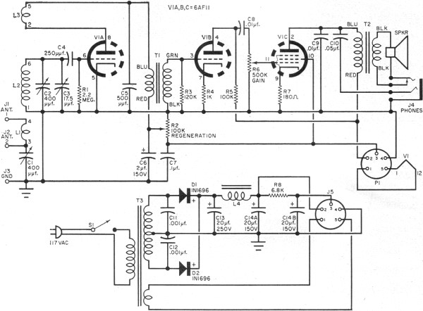
One Receiver
RF Cafe visitor David M. requested the scanning and posting of an article from the January 1963 edition of Popular Electronics, authored by Philip Hatfield from the Receiving Tube Department of General Electric. The article describes a straightforward design utilizing...

RF Remote Control Encoder and Decoder Chips Explained
Creating a universal remote control system has become quite straightforward. One can acquire the necessary chips, assemble them, and the high-tech remote control device will be operational. This document discusses specific remote control chips designed for this purpose. The IC...

Rf-Type Battery Charger Circuit
This type of charger transfers RF energy from an inductor (L2) to an external pickup coil. The pickup coil is connected to a rectifier and a battery that requires charging. This design is advantageous as it eliminates the need for...

2 Channels RF remote control
Remote controls are often needed to manage various electric devices. There are several types of remote controls available, including infrared, RF (Radio Frequency), and SMS. Basic short-range remote controls primarily utilize infrared and RF technology. A limitation of infrared is...

DF data transmission module and the super-regenerative receiver module
The DF data transmission module operates at a frequency of 315 MHz and utilizes a surface acoustic wave (SAW) resonator for frequency stabilization, ensuring high frequency stability. The frequency drift remains minimal, at only 3 x 10^-6, across a temperature...

RF Wireless Data Transfer communication Circuit diagram
RF Wireless Data Transfer communication circuit diagram. A wireless communication interface was implemented to facilitate data transfer from one point to another using RF technology.
The RF Wireless Data Transfer communication circuit utilizes radio frequency (RF) technology to establish a wireless...
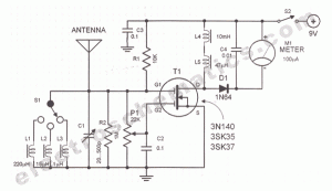
RF field strength meter circuit
A sensitive and reliable RF field strength meter is an invaluable instrument in amateur radio and in the radio-controlled model area. A field strength meter is.
A radio frequency (RF) field strength meter is a specialized device used to measure the...
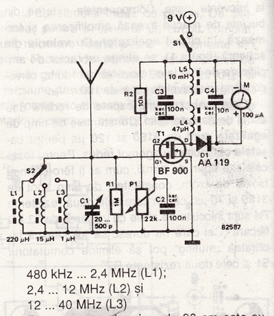
Radio Field Indicator Circuit
An RF field indicator is needed to verify power stages and transmitter antennas. This radio field indicator allows for the measurement of radiated energy from antennas.
An RF field indicator is a crucial device in the field of telecommunications and broadcasting....