


10 Bit A-D converter circuit
#A-D converter
#10-bit
#LT1016
#capacitor
#voltage measurement
#linear charging
#pulse control
#2.5V range
#resistance

Description: Each time a pulse is applied to the control input for conversion, Q1 resets the 1000 pF capacitor to 0 V. This resetting action takes 200 ns, after which the capacitor begins to charge linearly. In precisely 10 microseconds, it reaches a voltage of 2.5 V. This ramping voltage, which occurs over 10 microseconds, is applied to the positive input of the LT1016 operational amplifier. The LT1016 compares this ramp voltage (Ex) to an unknown voltage at its negative input. For a 0 V to 2.5 V range, Ex is connected through a 2.5 kΩ resistor. In the case of a 0 V to 10 V range, the 2.5 kΩ resistor is grounded, and Ex is connected through a 7.5 kΩ resistor. The output of the LT1016 is a pulse whose width is directly proportional to the value of Ex. This pulse width is utilized to gate a clock operating at 100 MHz. The 100 MHz clock pulse bursts that appear at the output are proportional to Eg for a 0 V to 10 V input, generating 1024 pulses at full scale from 512 to 5.00 V, among other values.
The described circuit operates as a precise analog-to-digital converter (ADC) using the LT1016 operational amplifier. The system initiates a conversion process when a control pulse is applied, triggering Q1 to reset the capacitor. The 1000 pF capacitor's rapid discharge and subsequent linear charging behavior are critical for generating a stable ramp voltage. The ramp voltage, reaching 2.5 V over 10 microseconds, serves as the reference signal for the LT1016, which functions as a comparator.
The comparator's role is to assess the relationship between the ramp voltage (Ex) and the unknown voltage applied to its negative input. The choice of resistor values (2.5 kΩ and 7.5 kΩ) determines the scaling of the input voltage range. For lower voltage ranges (0 V to 2.5 V), the 2.5 kΩ resistor allows for a direct comparison, while the grounded 2.5 kΩ resistor in the higher range (0 V to 10 V) adjusts the input sensitivity accordingly.
The output pulse width generated by the LT1016 is a critical parameter for subsequent digital processing. This pulse width, which varies with the input voltage Ex, is used to gate a high-frequency clock signal of 100 MHz. The resulting clock pulses are quantized into 1024 discrete levels, providing a high-resolution output suitable for digital applications. The relationship between the output pulses and the input voltage allows for accurate representation and processing of analog signals in digital systems, making this circuit highly effective for applications requiring precise voltage measurements and conversions.Each time a pulse is applied to the conversion of the control input, Ql resets the 1000 pF capacitor to 0 V. This action takes 200 ns to reset the falling edge of the convert command pulse, the capacitor begins to charge linearly.
In exactly 10 microseconds, it loads to 2.5 V. The ramp is 10 microseconds applied to the positive input of the LTl016. The LT1016 compares the ramp Ex, the unknown, its negative input. For a 0 V - 2.5 V range, Ex is applied to the resistance of 2.5 k ohm. On a 0 V - 10 V, 2.5 k ohm resistor is grounded, and Ex is applied to the resistance of 7.5 k ohm. LT1016 output is a pulse whose width is directly dependent on the value of Ex. This pulse width is used at the gate a clock at 100 MHz. The 100 MHz clock pulse bursts that appear at the output is proportional to Eg for a 0 V - 10 V input, 1024 pulses appear full scale from 512 to 5.00 V, etc.
The described circuit operates as a precise analog-to-digital converter (ADC) using the LT1016 operational amplifier. The system initiates a conversion process when a control pulse is applied, triggering Q1 to reset the capacitor. The 1000 pF capacitor's rapid discharge and subsequent linear charging behavior are critical for generating a stable ramp voltage. The ramp voltage, reaching 2.5 V over 10 microseconds, serves as the reference signal for the LT1016, which functions as a comparator.
The comparator's role is to assess the relationship between the ramp voltage (Ex) and the unknown voltage applied to its negative input. The choice of resistor values (2.5 kΩ and 7.5 kΩ) determines the scaling of the input voltage range. For lower voltage ranges (0 V to 2.5 V), the 2.5 kΩ resistor allows for a direct comparison, while the grounded 2.5 kΩ resistor in the higher range (0 V to 10 V) adjusts the input sensitivity accordingly.
The output pulse width generated by the LT1016 is a critical parameter for subsequent digital processing. This pulse width, which varies with the input voltage Ex, is used to gate a high-frequency clock signal of 100 MHz. The resulting clock pulses are quantized into 1024 discrete levels, providing a high-resolution output suitable for digital applications. The relationship between the output pulses and the input voltage allows for accurate representation and processing of analog signals in digital systems, making this circuit highly effective for applications requiring precise voltage measurements and conversions.Each time a pulse is applied to the conversion of the control input, Ql resets the 1000 pF capacitor to 0 V. This action takes 200 ns to reset the falling edge of the convert command pulse, the capacitor begins to charge linearly.
In exactly 10 microseconds, it loads to 2.5 V. The ramp is 10 microseconds applied to the positive input of the LTl016. The LT1016 compares the ramp Ex, the unknown, its negative input. For a 0 V - 2.5 V range, Ex is applied to the resistance of 2.5 k ohm. On a 0 V - 10 V, 2.5 k ohm resistor is grounded, and Ex is applied to the resistance of 7.5 k ohm. LT1016 output is a pulse whose width is directly dependent on the value of Ex. This pulse width is used at the gate a clock at 100 MHz. The 100 MHz clock pulse bursts that appear at the output is proportional to Eg for a 0 V - 10 V input, 1024 pulses appear full scale from 512 to 5.00 V, etc.
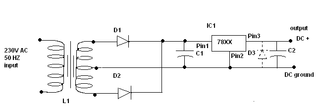
Power supply circuit design
C1 is a 1000 microfarad aluminum electrolytic capacitor. For loads less than 100mA, a 220 microfarad capacitor can be substituted. The voltage rating should be 2.5 times the output voltage.
C1 serves as a critical component in various electronic circuits, particularly...

Capacitor internal resistor meter
The design presented here works by applying a 50kHz, 200mV square wave to the capacitor under test, in series with a 10 Ohm resistor. The AC voltage appearing across that resistor is measured and displayed on a meter. So the...

ELF MONITOR
The capacitor instrument is not intended for measuring the capacitance of capacitors; rather, it is designed to identify whether a capacitor is functional or defective, as well as to detect short circuits or open circuits. This functionality provides reliable quality...

a more practical capacitor powered
The inexpensive flashlight utilized a small (0.22 Farad) capacitor for energy storage, which provided approximately 6.6 Joules of energy, significantly less than 1/1000th of the energy contained in a single AA alkaline cell. As a standard "super capacitor," it had...
ELF MONITOR
The capacitor instrument is not intended for measuring the capacitance of capacitors; rather, it is designed to identify whether a capacitor is functional or defective, as well as to detect short circuits or open circuits. This functionality provides reliable quality...

EIGHT CHANNEL COMPUTERIZED 3SUP1 SUP SUB2 SUB DIGIT_VM
Displays up to eight different DC voltages on a CRT terminal of a microprocessor under keyboard control, using BASIC commands and a BASIC routine provided in the article. Utilizes a modified Motorola MC14433 dual-lamp integrating analog-to-digital converter. An unknown voltage...
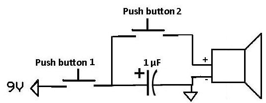
Apply a Pulse to a Speaker Using a Capacitor
This project demonstrates how a capacitor can supply a pulse signal to a speaker. A capacitor is charged and then discharges its voltage to a speaker, which acts as a transducer that converts electrical signals into sound. The result is...

14 Bit A-D Converter with ICL7134B
The ICL7134B circuit is a bipolar input analog-to-digital (A/D) converter that employs two AM25L03 chips to create a 14-bit successive approximation register. The comparator features a two-stage amplifier, HA2605, which is utilized to mitigate settling time issues at the summing...

Circuit to Measure Power Supply Voltages
To obtain the power supply graphs on the previous page, the circuit is designed to independently monitor the power sources with the addition of a few resistors. Diode D3 allows the solar panel voltage to charge the batteries, while the...